
A U-shaped quartz tube drying device

A drying device, quartz tube technology, applied in drying, drying machine, drying gas arrangement, etc., can solve the problem of insufficient drying of quartz tubes, achieve guaranteed drying time, efficient and sufficient drying process, highly targeted effects

Active Publication Date: 2021-10-12
新沂市赛立科石英制品有限公司
View PDF7 Cites 0 Cited by
  • Summary
  • Abstract
  • Description
  • Claims
  • Application Information

AI Technical Summary

Problems solved by technology

The drying device for quartz tube production is equipped with the first motor to drive the rotating rod to rotate. The first roller, the second roller and the belt form a transmission system to transport the fixed box. During the transmission process, the rack drives the drive rod through the gear. Rotate, the push bar on the driving rod makes the quartz tube rotate, and in the process of transmission, under the action of hot air, every place on the surface of the quartz tube can be air-dried; although this device can be used to remove water from the quartz tube Drying effect, but the quartz tubes cannot be dried efficiently and fully one by one. For this reason, a U-shaped quartz tube drying device is now provided to solve the above technical problems

Method used


Image

  • A U-shaped quartz tube drying device
  • A U-shaped quartz tube drying device
  • A U-shaped quartz tube drying device

Examples


Embodiment 1

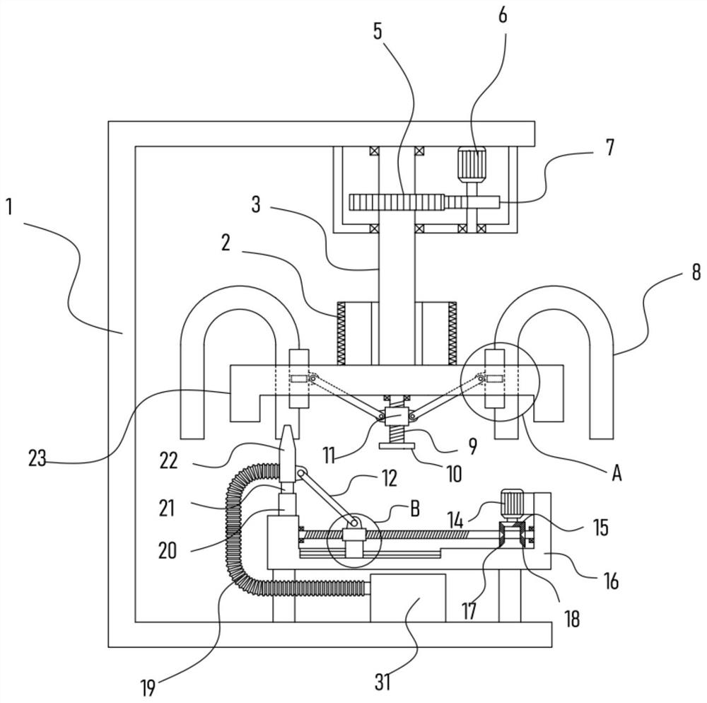
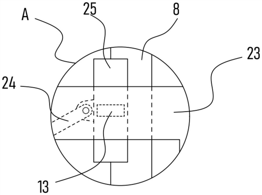
[0022] see Figure 1-4 , a U-shaped quartz tube drying device, comprising a fixed frame 1, a bracket 16 is fixed on the fixed frame 1, a turntable 23 is mounted on the fixed frame 1, and a rotating disk 23 is vertically fixed and pivotally connected to the fixed frame. The rotating shaft 3 on the frame 1, the fixed frame 1 is provided with a driving mechanism for driving the rotating shaft 3 step-by-step rotation, and the rotating disk 23 is provided with a locking mechanism for fixing the U-shaped quartz tube 8, so An annular heater 2 is sleeved on the rotating shaft 3, a blower 31 is fixed on the fixed frame 1, and the outlet end of the blower 31 is connected with a nozzle 22 vertically corresponding to the mouth of the U-shaped quartz tube 8 through a bellows 19. , the bracket 16 is fixed with a servo motor II14, and the servo motor II14 is drivingly connected with a lifting mechanism for driving the lifting mechanism of the spray head 22.

[0023] The turntable 23 provide...

Embodiment 2

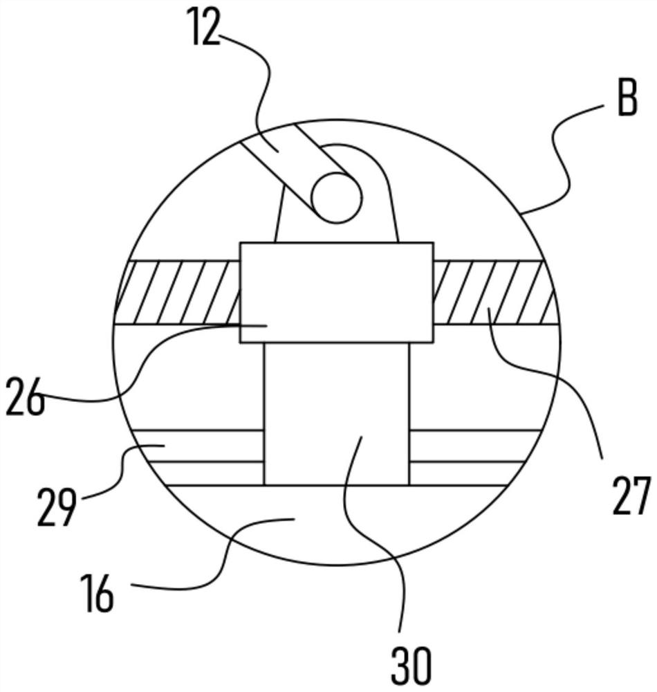
[0029] On the basis of Embodiment 1, in addition, this device is also provided with a lifting mechanism including a screw rod 27 that is rotatably installed on the bracket 16. The screw rod 27 is threaded with a screw rod sleeve block 26, and the bottom of the nozzle 22 is vertical. A guide rod 21 is directly fixed, and the sliding sleeve on the guide rod 21 is provided with a guide sleeve 20 fixed on the bracket 16. A pull rod 12 is hinged between the guide sleeve 20 and the screw cover block 26. The lifting mechanism also includes a servo motor II14 The incomplete bevel gear 15 is driven to rotate, and the incomplete bevel gear 15 is alternately meshed with a bevel gear I17 and a bevel gear II18 sleeved and fixed on the screw rod 27 .

[0030] Through the above settings, the servo motor II14 drives the incomplete bevel gear 15 to rotate, and the incomplete bevel gear 15 is alternately meshed with the bevel gear I17 and the bevel gear II18. At this time, the screw 27 rotates a...


PUM


Abstract

The invention discloses a U-shaped quartz tube drying device, which relates to the technical field of quartz tube processing. The turntable is provided with a locking mechanism for fixing the U-shaped quartz tube, and a blower is fixed on the fixed frame, and the outlet end of the blower is connected with a nozzle vertically corresponding to the mouth of the U-shaped quartz tube through a corrugated tube. The servo motor II is fixed, and the servo motor II is driven and connected with a lifting mechanism for driving the nozzle lifting mechanism; the present invention can clamp and fix a plurality of U-shaped quartz tubes on the turntable through the set clamping mechanism, and the set driving mechanism It can drive the rotating shaft to drive the turntable to rotate step by step, so that the nozzles can be aligned with the U-shaped quartz tube nozzles on the turntable one by one, and the U-shaped quartz tubes can be fully dried one by one. The drying process is highly targeted, and the drying The time is guaranteed and the drying process is efficient and sufficient.

Description

technical field [0001] The invention relates to the technical field of quartz tube processing, in particular to a U-shaped quartz tube drying device. Background technique [0002] Quartz tube is a special industrial technical glass made of silica. It is a very good basic material. Quartz glass has a series of excellent physical and chemical properties. It is used in electric fire barrels, electric ovens, and electric heaters to generate heat. Quartz tubes can be roughly divided into the following types: transparent quartz tubes, ultraviolet filter quartz tubes, colored quartz tubes, etc. During the production and processing of quartz tubes , it needs to be dried. [0003] The patent with authorized notification number CN210165717 U discloses a drying device for quartz tube production, which includes a housing, a first motor is fixedly installed on the back of the housing, and a penetrating motor is fixedly installed on the front of the output shaft of the first motor. The ...

Claims


Application Information

Patent Timeline
Patent Type & Authority Patents(China)
IPC IPC(8): F26B11/18F26B21/00F26B25/02F26B25/18F26B25/00
CPCF26B11/18F26B21/001F26B21/004F26B25/003F26B25/02F26B25/185
Inventor 胡冬
Owner 新沂市赛立科石英制品有限公司
Learn More