Efficient hot-blast stove for grain dryer

A technology of grain dryer and hot air stove, which is applied in the direction of dryer, drying, grain drying, etc., can solve the problems of grain bursting, grain pollution, grain mildew in grain depots, etc., and achieve the reduction of heating process and scope of application Wide, time-saving effects

Inactive Publication Date: 2016-09-07
ANHUI GUFENG MECHANICAL TECH CO LTD
View PDF9 Cites 3 Cited by
  • Summary
  • Abstract
  • Description
  • Claims
  • Application Information

AI Technical Summary

Problems solved by technology

In the main grain producing areas, due to the large output and insufficient drying space, the moisture in the grain purchased by the grain depot often exceeds the safe water content, which is the main factor causing the grain mildew in the grain depot, especially when the grain purchase period is catching up with the continuous cloudy days, it is even more serious. In this way, in addition, even if the moisture content of the grain does not exceed the safe moisture content when entering the warehouse, due to spontaneous combustion and moisture return, the grain stored in the warehouse needs to be dried regularly to ensure that the grain does not go moldy. The grain is often not dried on time, which causes the grain in the grain depot to become mildewed. Therefore, people use dryers to dry the moisture in the grain. Because the existing grain drying technology is to directly input the hot smoke generated by fuel combustion into the The grain drying layer of the grain dryer, this direct heating method will cause pollution to the grain, and at the same time, the temperature of the hot smoke generated by fuel combustion cannot be controlled, and the excessive temperature will cause the grain to burst

Method used


Image

  • Efficient hot-blast stove for grain dryer
  • Efficient hot-blast stove for grain dryer

Examples


Embodiment Construction

[0014] The following will clearly and completely describe the technical solutions in the embodiments of the present invention with reference to the accompanying drawings in the embodiments of the present invention. Obviously, the described embodiments are only some, not all, embodiments of the present invention.

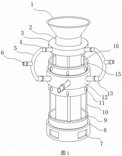
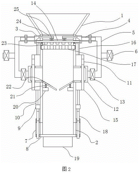
[0015] refer to Figure 1-2 , a high-efficiency hot air stove for grain dryers, comprising a furnace body 1, a base 19 is provided at the lower end of the furnace body 1, a feeding funnel 1 is provided at the upper end of the base 19, and the feeding funnel 1 and the furnace body 2 Internally connected, the outer side of the furnace body 2 is surrounded by a first fixed ring 3, a second fixed ring 12 and a discharge body 8 from top to bottom, and a number of first discharge ports 7 are arranged around the outside of the discharge body 8 The inner side of the second fixed ring 12 is provided with a second sealing plate 15, the inner side of the discharge body 8 is pro...


PUM


Abstract

The invention discloses an efficient hot-blast stove for a grain dryer. The efficient hot-blast stove for the grain dryer comprises a stove body, wherein a base is arranged at the lower end of the stove body; a feeding funnel is arranged at the upper end of the base and communicates with the inside of the stove body; a first fixing ring, a second fixing ring and a discharging body are successively arranged on the outer side of the stove body from top to bottom in a surrounding manner; a plurality of first discharging openings are formed in the outer side of the discharging body in a surrounding manner; a second seal plate is arranged on the inner side of the second fixing ring; a first seal plate is arranged on the inner side of the discharging body; a plurality of second discharging openings are formed in the outer side of the first seal plate in a surrounding manner; and the first fixing ring is connected with the second seal plate through a plurality of second connecting rods. By the efficient hot-blast stove for the grain dryer, moisture can be quickly removed from the drying device, by setting hot air provided by the hot-blast stove, the heating process of the traditional dryer is omitted, service time is saved, the overall efficiency of the dryer is improved, and grains are dried in such a circulating manner and then are discharged until water of the grains reaches a specified value.

Description

technical field [0001] The invention relates to the technical field of grain hot blast stove equipment, in particular to a high-efficiency hot blast stove used for grain dryers. Background technique [0002] As we all know, when the temperature and humidity conditions in the environment where the food is located meet the growth and reproduction of microorganisms, mildew will occur. That is to say, moisture and temperature are two important factors for the reproduction of microorganisms such as mold in grain. In general, controlling the grain moisture below the safe moisture level may prevent the grain from going moldy. At present, the method for reducing grain moisture is the spontaneous combustion drying method. In the main grain producing areas, due to the large output and insufficient drying space, the moisture in the grain purchased by the grain depot often exceeds the safe water content, which is the main factor causing the grain mildew in the grain depot, especially ...

Claims


Application Information

Patent Timeline
Patent Type & Authority Applications(China)
IPC IPC(8): F26B21/00A23B9/08
CPCA23B9/08F26B21/001F26B2200/06
Inventor 刘吉勇
Owner ANHUI GUFENG MECHANICAL TECH CO LTD
Why Eureka
Try Eureka