Switching apparatus for carrying and disconnecting electric currents, and switchgear having a switching apparatus of this kind

A technology for switching devices and cutting off current, which is applied in high-voltage/high-current switches, electric switches, electronic switches, etc. It can solve the problems of switch equipment failure, switch contact welding, etc., and achieve the effect of reducing current load

Active Publication Date: 2020-08-04
EATON INTELLIGENT POWER LIMITED
View PDF17 Cites 0 Cited by
  • Summary
  • Abstract
  • Description
  • Claims
  • Application Information

AI Technical Summary

Problems solved by technology

[0005] This avoids the formation of arcs during the contact bouncing phase, which could result in welding of the switching contacts and thus a possible failure of the switching device

Method used


Image

  • Switching apparatus for carrying and disconnecting electric currents, and switchgear having a switching apparatus of this kind
  • Switching apparatus for carrying and disconnecting electric currents, and switchgear having a switching apparatus of this kind
  • Switching apparatus for carrying and disconnecting electric currents, and switchgear having a switching apparatus of this kind

Examples


Embodiment Construction

[0024] In the following, identical, functionally identical and functionally related elements are identified with the same reference numerals. Absolute values ​​are given below by way of example only, which do not constitute a limitation.

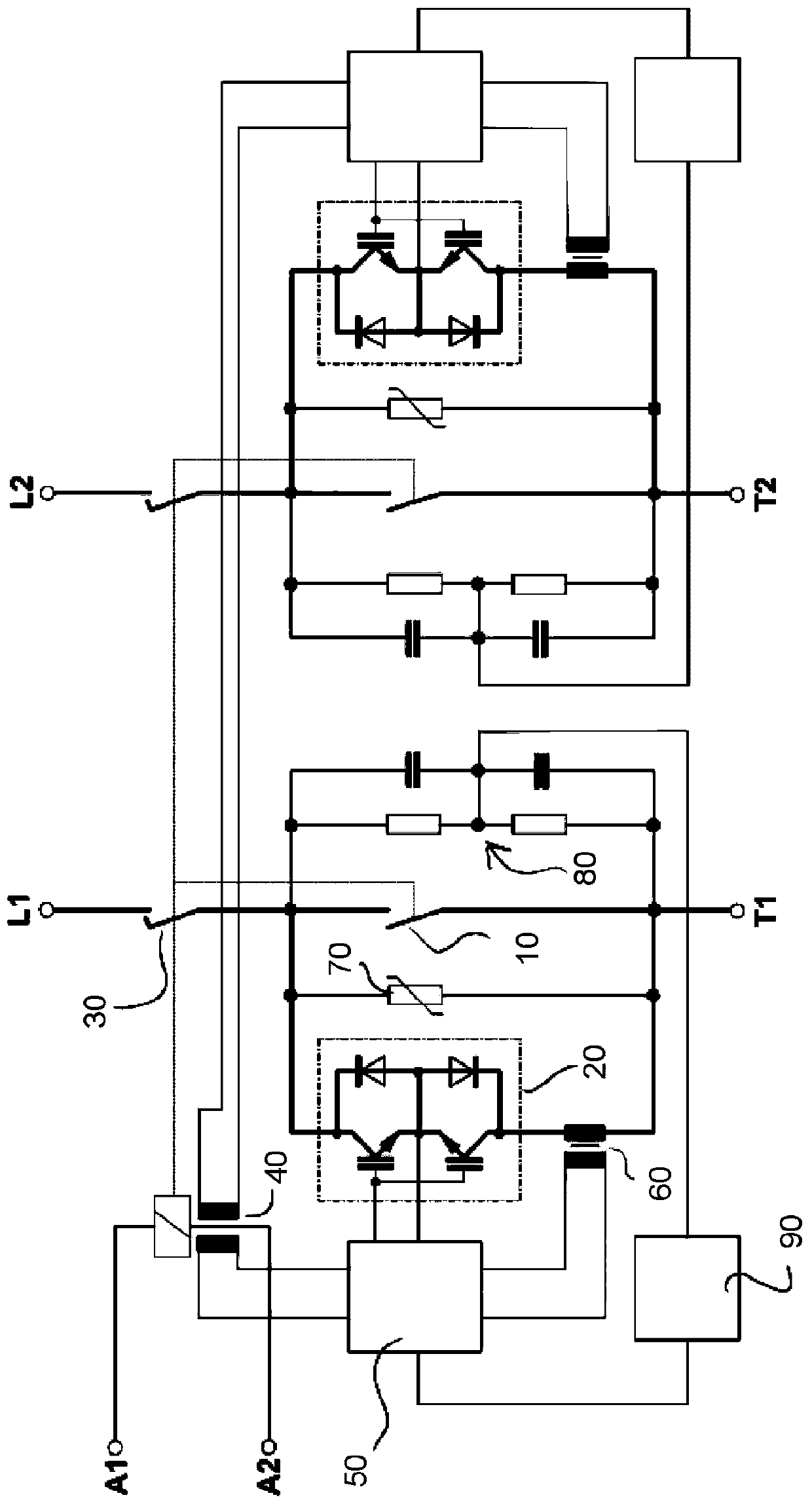
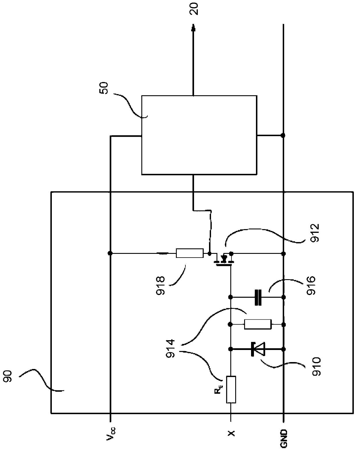
[0025] figure 1 is a block diagram of a switching device for a polarity-independent 2-pole switchgear. The pole-specific connections of the switching device are denoted L1, T1 and L2, T2, respectively. As far as the circuit is concerned, this switching device roughly corresponds to that described in German patent application laid-open DE 10 2013 114 259 A1 and in that case in figure 1 device shown in . Compared to this known device, the device described below differs in the control circuit 90, which is adapted for the specific control of the semiconductor switch 20, which will be explained in more detail below.

[0026] For each pole, such as figure 1 The switching devices shown each have a parallel circuit of a first mechanical (arcing...


PUM


Abstract

The invention discloses a switching apparatus for carrying and disconnecting electric currents, comprising a first mechanical contact arrangement (10), a second mechanical contact arrangement (30) which is connected in series with the first mechanical contact arrangement, a semiconductor switch (20) which is connected in parallel with the first mechanical contact arrangement, and a switching electronics system (50) which is designed to switch on and switch off the semiconductor switch (20), wherein the switching apparatus is designed in such a way that, during a switching process, the two mechanical contact arrangements (10, 30) are closed with a time delay in relation to one another. The invention further provides a control circuit (90) which is designed to ascertain a voltage across thefirst mechanical contact arrangement (10) and to generate an actuation signal for the switching electronics system (50), which actuation signal switches on the semiconductor switch (20), depending onthe ascertained voltage.

Description

technical field [0001] The invention relates to a switchgear for conducting and breaking current, in particular a hybrid switching arrangement for conducting and breaking high direct current as well as low frequency alternating current, and a switchgear having such a switchgear. Background technique [0002] An advantageous concept of an overhybrid switching configuration is described in German patent application laid-open DE 10 2013 114 259 A1, in which the current load of the power semiconductors is temporally reduced in order to achieve the longest possible life expectancy and the smallest possible dimensions. Minimization, which is especially important for power contactors in the hundreds of amperes range. In order to minimize the load current flowing through the power semiconductors over time, the commutation times are detected by current transformers and the current flow through the semiconductors is only maintained until the open mechanical contact gap has reached suf...

Claims


Application Information

Patent Timeline
Patent Type & Authority Applications(China)
IPC IPC(8): H01H33/59H01H9/54
CPCH01H9/542H01H33/596H01H2009/546H01H9/30H01H33/59H03K17/56
Inventor J·迈斯纳G·施米茨K·施罗德M·沃朗O·克雷夫特M·乌德尔霍芬
Owner EATON INTELLIGENT POWER LIMITED
Why Eureka
Try Eureka