Treatment device for waste medical masks

A processing device and mask technology, applied in the medical field, can solve problems such as single function of the processing device, and achieve the effect of realizing processing speed and adjustment.

Inactive Publication Date: 2020-08-07
王英
View PDF8 Cites 8 Cited by
  • Summary
  • Abstract
  • Description
  • Claims
  • Application Information

AI Technical Summary

Problems solved by technology

[0002] The processing device for medical waste masks is a commonly used equipment in the medical field, but the general medical waste mask processing device has a single function

Method used


Image

  • Treatment device for waste medical masks
  • Treatment device for waste medical masks
  • Treatment device for waste medical masks

Examples


specific Embodiment approach 1

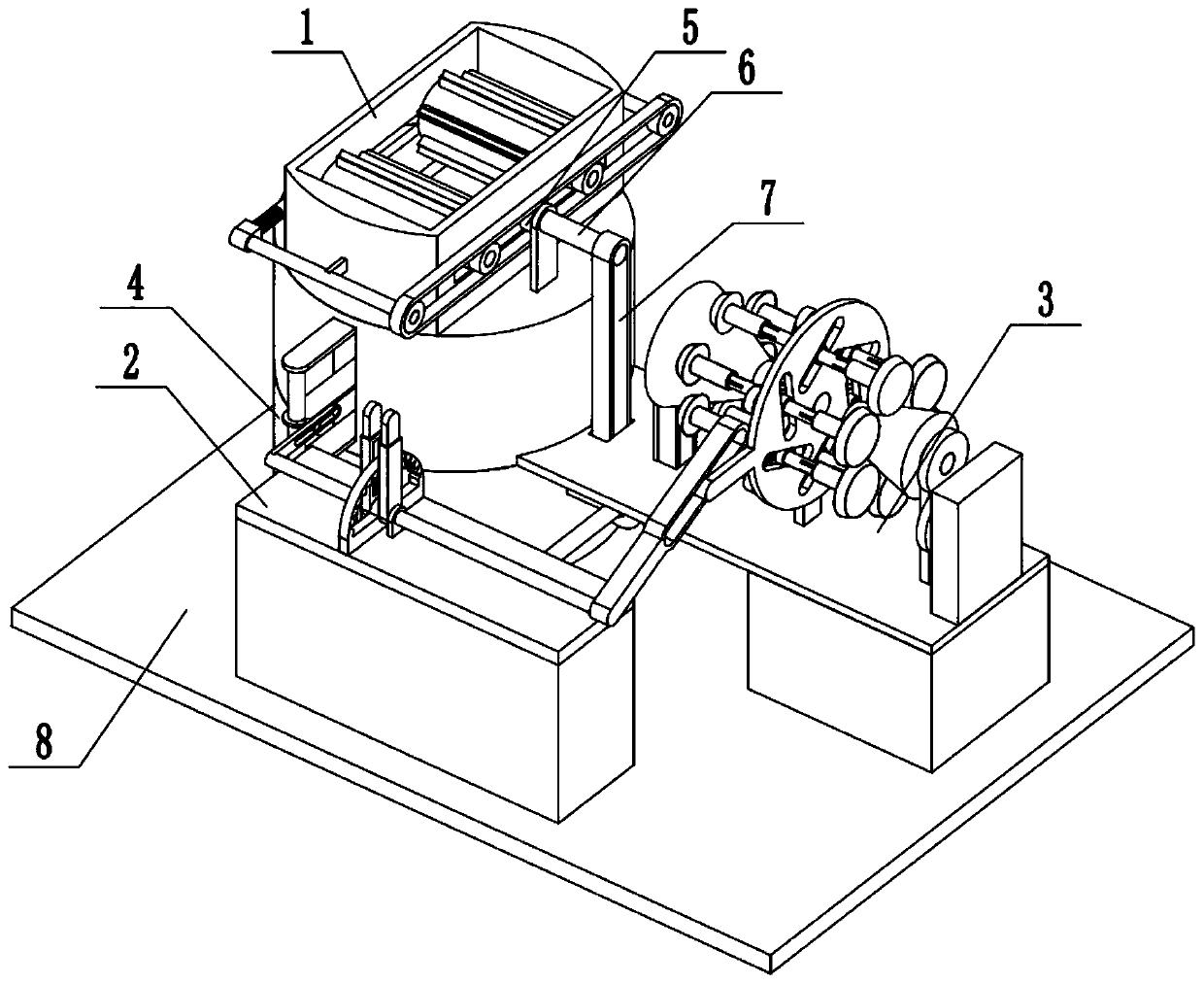
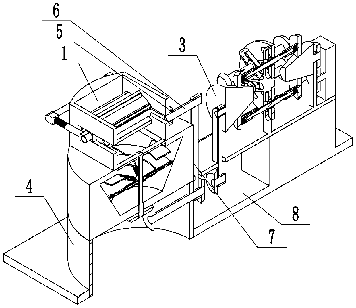
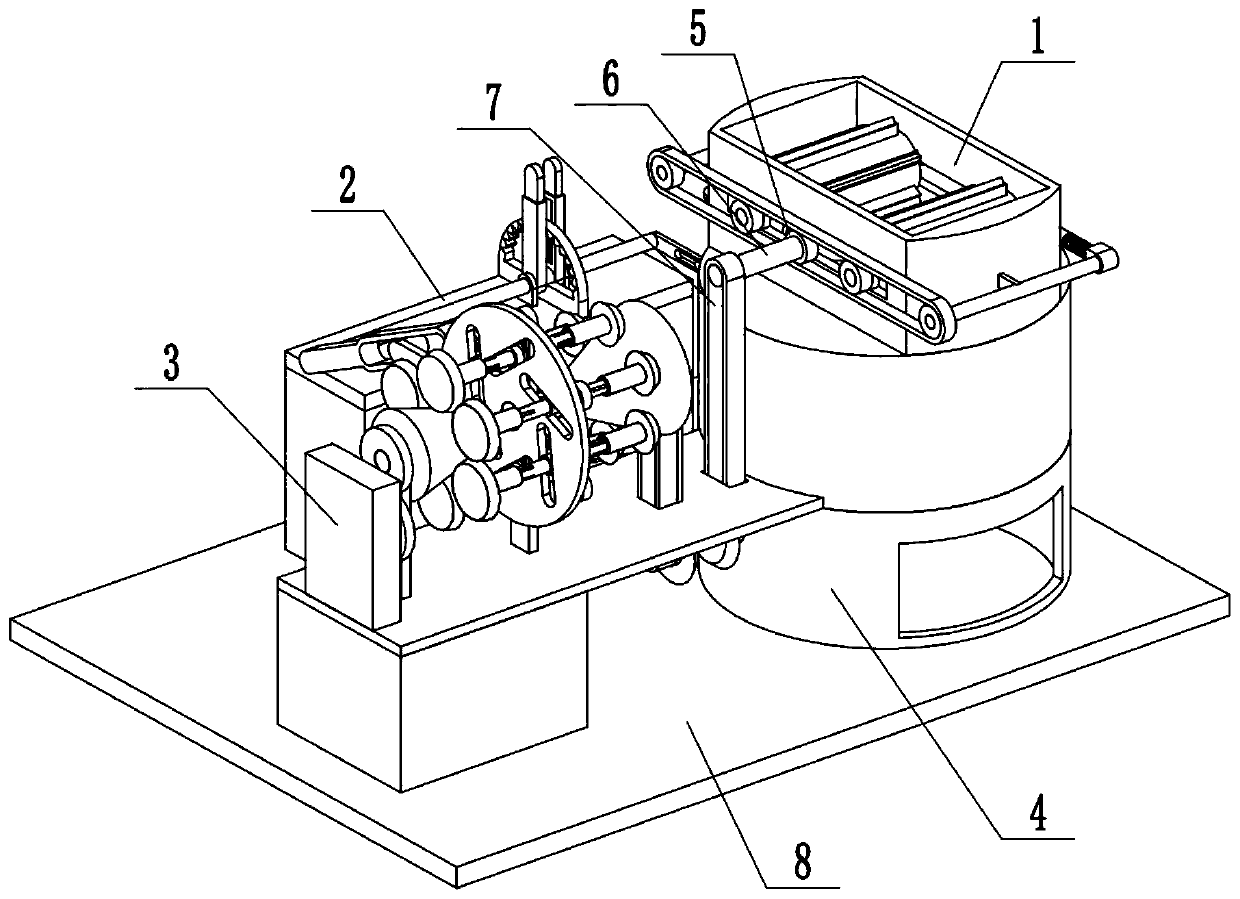
[0029] Combine below Figure 1-12 Describe this embodiment, a treatment device for medical waste masks, including a crushing assembly 1, a switching assembly 2, a power source assembly 3, a separation assembly 4, a transmission pulley-5, a transmission pulley rod-6, and a transmission belt A7 , Underframe 8, the transmission belt A7 is connected with the transmission pulley rod-6, the crushing assembly 1 is connected with the separation assembly 4, the switching assembly 2 is connected with the crushing assembly 1, the switching assembly 2 is connected with the separation assembly The body 4 is connected, the power source assembly 3 is connected with the chassis 8, the separation assembly 4 is connected with the chassis 8, and the switch assembly 2 is connected with the chassis 8.

specific Embodiment approach 2

[0031] Combine below Figure 1-12 Describe this embodiment, this embodiment will further explain Embodiment 1, the crushing assembly 1 includes a crushing outer frame 1-1, a carrying outer frame 1-2, a side wall sliding column 1-3, and a middle end sliding plate 1-4 , side wall bracket 1-5, hinged sliding rod one 1-6, hinged sliding rod push spring one 1-7, hinged sliding rod two 1-8, side wall pulley one 1-9, side wall belt one 1-10 , Side wall pulley 2 1-11, carrying roller 1-12, lower bevel gear 1-13, lower bevel gear rotating column 1-14, rectangular slider 1-15, tapered slider 1-16 , Slider bracket 1-17, inner spring 1-18, crushing blade 1-19, inner sleeve 1-20, inner spring 2 1-21, rectangular slider 2 1-22, spherical clamping rod 1 1-23, spherical clamping rod push spring 1-24, spherical clamping slot 1-25, carrying prismatic rod 1-26, prismatic rod sliding frame 1-27, sliding frame sliding column 1-28, sliding frame sliding column spring 1-29, the carrying outer fram...

specific Embodiment approach 3

[0033] Combine below Figure 1-12 Describe this embodiment, this embodiment will further explain the first embodiment, the switching assembly 2 includes a switching bottom plate 2-1, a middle end bottom plate 2-2, a middle end card slot 2-3, and a driving rotating rod 2-4 , manual casing one 2-5, push lever one 2-6, push lever two 2-7, manual casing two 2-8, drive rotating rod two 2-9, push spring one 2-10, press Moving spring two 2-11, the middle end base plate 2-2 is fixedly connected with the switching base plate 2-1, the middle end card slot 2-3 is arranged on the middle end base plate 2-2, the driving rotating rod one 2-4, the driving rotating rod Two 2-9 are rotationally connected with the switching base plate 2-1, manual casing one 2-5, manual casing two 2-8 are fixedly connected with driving rotating rod one 2-4, driving rotating rod two 2-9 respectively, press Rod one 2-6, push rod two 2-7 are respectively connected with manual sleeve pipe one 2-5, manual sleeve pipe...


PUM


Abstract

The invention relates to the medical field, in particular to a treatment device for waste medical masks. Crushing of the waste medical masks can be realized; the crushing effect on the waste medical masks can be adjusted according to actual conditions; classification of the crushed waste medical masks can be realized, and separation of cloth and nose clip metal wires can be realized; and the processing speed of the device can be adjusted according to actual conditions. The device comprises a crushing assembly body, a switching assembly body, a power source assembly body, a separation assemblybody, a first transmission belt wheel, a first transmission belt wheel rod, a transmission belt A and an underframe, so that the ratio of the distance between the transmission position of a first conical wheel and a first conical roller and the rotation axis of the first conical roller to the distance between the transmission position of a second conical wheel and a second conical roller and the rotation axis of the second conical roller is changed, the transmission relation is changed at the same time, the rotation speed output by a first bevel gear, the transmission belt A and an outer bevelgear is changed, and then the processing speed of the device is adjusted.

Description

technical field [0001] The invention relates to the medical field, in particular to a treatment device for medical waste masks. Background technique [0002] The processing device of medical waste masks is a commonly used equipment in the medical field, but the processing device of general medical waste masks has a single function. Contents of the invention [0003] The purpose of the present invention is to provide a treatment device for medical waste masks, which can realize the crushing of medical waste masks; and can adjust the crushing effect of medical waste masks according to the actual situation; can realize the classification of the crushed medical waste masks, It can realize the separation of the cloth and the metal wire of the nose clip; the processing speed of the device can be adjusted according to the actual situation. [0004] The purpose of the present invention is achieved through the following technical solutions: [0005] A treatment device for medical...

Claims


Application Information

Patent Timeline
Patent Type & Authority Applications(China)
IPC IPC(8): B02C18/12B02C18/18B02C18/24B02C18/22B02C18/16B09B3/00
CPCB02C18/0084B02C18/12B02C18/16B02C18/18B02C18/2225B02C18/24B02C2201/06B09B3/00
Inventor 郭淑琴
Owner 王英
Why Eureka
Try Eureka