A multifunctional metal plate welding device for building construction

A technology for sheet metal and building construction, applied in welding equipment, auxiliary devices, auxiliary welding equipment, etc., can solve the problems that affect the user's experience of using welding devices, the health hazards of smoke and dust workers, and the lack of dust removal structures, and achieve rich functions. , Improve the user experience, the effect of convenient use

Active Publication Date: 2022-04-12
抚州吉远企业管理咨询有限公司
View PDF1 Cites 0 Cited by
  • Summary
  • Abstract
  • Description
  • Claims
  • Application Information

AI Technical Summary

Problems solved by technology

[0004] However, due to the lack of a corresponding dust removal structure in this welding device, a large amount of smoke and dust will be emitted when the welding device is in use. The scattering of smoke and dust will cause harm to the health of the staff and affect the user's experience of using the welding device.

Method used


Image

  • A multifunctional metal plate welding device for building construction
  • A multifunctional metal plate welding device for building construction
  • A multifunctional metal plate welding device for building construction

Examples


Embodiment 1

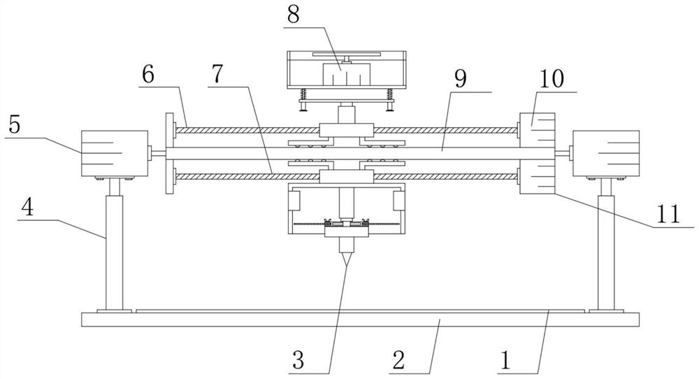
[0024] see Figure 1-Figure 4 , the present invention provides a technical solution: a multifunctional metal plate welding device for building construction, including a first support plate 2, a second support plate 9 is arranged above the first support plate 2, and the two sides of the second support plate 9 A first drive motor 5 is provided at the end, a first electric telescopic rod 4 corresponding to the first drive motor 5 is provided at both ends of the upper surface of the first support plate 2, and a third electric telescopic rod 4 is provided at one end of the lower surface of the second support plate 9 The drive motor 11, the output end of the third drive motor 11 is provided with a second limit screw 7, and one end of the second limit screw 7 is provided with a welding mechanism 3;

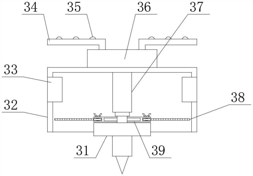
[0025] In order to make the use of the welding mechanism 3 more convenient, in this embodiment, preferably, the welding mechanism 3 includes a collecting cover 32, and the upper surface ...

Embodiment 2

[0031] On the basis of Embodiment 1, in order to make the function of the welding device more abundant, in this embodiment, preferably, one end of the upper surface of the second support plate 9 is fixed with a second drive motor 10 by bolts, and the second drive motor 10 The output end is welded with a first limit screw 6, one end of the first limit screw 6 is provided with a grinding mechanism 8, and the second drive motor 10 is electrically connected to the power supply through a switch;

[0032] In order to enrich the functions of the grinding mechanism 8, the grinding mechanism 8 includes a fourth support plate 894, the lower surface of the fourth support plate 894 is welded with a third electric telescopic rod 81, and the bottom end of the third electric telescopic rod 81 is welded with the first electric telescopic rod 81. The second limit slider 82 corresponding to the limit screw rod 6, the lower surface two ends of the second limit slider 82 are welded with the second...


PUM


Abstract

The invention discloses a multifunctional metal plate welding device for building construction, which belongs to the technical field of welding devices and comprises a first support plate, a second support plate is arranged above the first support plate, and two ends of the second support plate are provided with The first drive motor, the two ends of the upper surface of the first support plate are provided with the first electric telescopic rod corresponding to the first drive motor, the lower surface of the second support plate is provided with the third drive motor, the third drive The output end of the motor is provided with a second limit screw, and one end of the second limit screw is provided with a welding mechanism. The welding mechanism includes a collection cover, and the upper surface of the collection cover is provided with a first stop corresponding to the second limit screw. A limit slider; the present invention is simple in structure, easy to use, and has a purification function, which can absorb and purify the smoke generated during welding, thereby removing harmful substances in the smoke and preventing the smoke from flying around, which is harmful to the health of the staff Harm.

Description

technical field [0001] The invention belongs to the technical field of welding devices, and in particular relates to a multifunctional metal plate welding device for building construction. Background technique [0002] Chinese patent (publication number is CN205660317U) discloses an automatic welding device, including: a base, a welding table protruding from the upper end of the base, a first mounting seat and a second mounting seat arranged on the bases on both sides of the welding table The mounting base, the first manipulator and the second manipulator respectively installed on the first mounting base and the second mounting base for grabbing the metal sheet to be welded, the welding frame erected corresponding to the welding table, the installation The power device on the welding frame, the lifting rod connected with the lower end of the power device, and the heating device installed at the lower end of the lifting rod. [0003] The utility model has the advantages of r...

Claims


Application Information

Patent Timeline
Patent Type & Authority Patents(China)
IPC IPC(8): B23K37/00B23K37/02B01D49/00B01D53/04B24B7/10B24B55/06
CPCB23K37/00B23K37/0252B01D49/00B01D53/04B24B7/10B24B55/06
Inventor 汤明
Owner 抚州吉远企业管理咨询有限公司
Why Eureka
Try Eureka