
Device and method for preventing biofouling of marine propeller

A marine propeller and biofouling technology, which is applied in the direction of pollution prevention methods, rotating propellers, ship cleaning devices, etc., can solve problems such as complex sea conditions, large propeller shapes, and difficulty in showing antifouling effects, and achieve huge market potential Effect

Inactive Publication Date: 2020-08-07
邱日
View PDF8 Cites 2 Cited by
  • Summary
  • Abstract
  • Description
  • Claims
  • Application Information

AI Technical Summary

Problems solved by technology

The advantage of this method is that it has no impact on the environment, and has the characteristics of small system volume, light weight, and flexible installation; at present, in order to prevent marine animals and plants from fouling the propeller, when designing the impressed current cathodic protection device, a special The antifouling electrodes used to prevent marine biofouling are set up. The actual application proves that the propeller antifouling electrodes have a certain effect on the prevention and control of marine biofouling. According to the design, the ClO produced by electrolysis of the antifouling electrodes - The purpose of antifouling can only be achieved when the concentration reaches 0.1ppm ~ 0.5ppm. However, the sea conditions in the actual marine environment are complex, and the propeller itself is huge and complex. It is difficult to ensure that any area of ​​the propeller blade will make ClO - Reach the lethal concentration, so it is difficult to reflect the expected antifouling effect
[0007] It can be seen that the current methods can only alleviate the biofouling of the propeller surface to a limited extent.

Method used


Image

  • Device and method for preventing biofouling of marine propeller
  • Device and method for preventing biofouling of marine propeller

Examples


Embodiment Construction

[0031] The following will clearly and completely describe the technical solutions in the embodiments of the present invention with reference to the accompanying drawings in the embodiments of the present invention. Obviously, the described embodiments are only some, not all, embodiments of the present invention. Based on the embodiments of the present invention, all other embodiments obtained by persons of ordinary skill in the art without making creative efforts belong to the protection scope of the present invention.

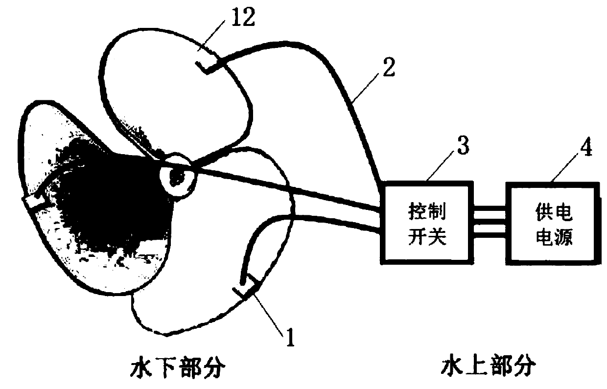
[0032] see figure 1 , a marine propeller anti-biofouling device of the present invention includes a control switch 3, a power supply 4, and a heating fixture 1, the heating fixture 1 is used to clamp and fix the blades of a marine propeller 12, and the heating fixture 1 passes through a cable 2 Connect the control switch 3, and further connect to the power supply 4. The power supply 4 supplies power to the heating fixture 1, and the marine propeller 12 is heat...


PUM


Abstract

The invention provides a device and a method for preventing biofouling of a marine propeller. The device comprises a marine propeller, a control switch, a power supply and a heating clamp, the heatingclamp is used for clamping and fixing marine propeller blades, the heating clamp is connected with the control switch through a cable and further connected to the power supply, the power supply supplies power to the heating clamp, the marine propeller is heated through the heating clamp, and the control switch is used for controlling heating time and setting a heating temperature threshold value.The invention provides an means for preventing biofouling of the surface of a blade which is installed on site, efficiently without dead corners. As long as the heating clamp is powered on for heating, heat can be transmitted to any metal conduction position along the metal blade surface of a propeller, no fouling dead angle is left, and revolutionary progress is brought to fouling prevention ofthe propeller. When the berthing time of a ship is over, the related heating clamps can be automatically unloaded under the repulsion effect of the electromagnets on the two sides, and adverse effectson normal work of the propeller are avoided.

Description

technical field [0001] The invention relates to a method for preventing biofouling on the blade surface of a propeller, covering propellers of different metal materials used by various ships in seawater, in particular to a device and method for preventing biofouling of a marine propeller. Background technique [0002] Propellers are key components of all types of boats. During the voyage, due to the scouring effect of the high-speed water flow generated by the rotation of the propeller, the growth of sea organisms on the propeller can be inhibited. However, during berthing, due to the long-term static immersion of the propeller in seawater, hard-shelled marine organisms such as barnacles will spontaneously attach to the metal surface, causing serious biofouling. When marine organisms such as barnacles attach to the propeller, it will inevitably change the hydrodynamic properties of the propeller, affect the normal working performance of the propeller, and cause many adverse...

Claims


Application Information

Patent Timeline
IPC IPC(8): B63H1/14B63B59/00B08B7/00B08B17/06
CPCB08B7/0071B08B17/06B63B59/00B63H1/14
Inventor 邱日邱子轩赵瑾
Owner 邱日
Learn More