
FF buried oil tank with anti-seepage well bases

A well seat and oil tank technology, applied in climate change adaptation, containers, packaging, etc., can solve the problems that affect the maintenance of staff, cannot solve the problem of water seepage, inconvenient discharge, etc., achieve long service life, good sealing effect, and improve timeliness effect

Inactive Publication Date: 2020-08-07
SICHUAN XINLEI BUILDING ENG CO LTD
View PDF14 Cites 0 Cited by
  • Summary
  • Abstract
  • Description
  • Claims
  • Application Information

AI Technical Summary

Problems solved by technology

In the existing FF buried oil tank, the operation well and the well base are mostly connected by flanges, which are mainly used to prevent fine sand from entering the operation well and affecting the later maintenance and repair operations, but this structure cannot solve the problem. Water seepage problem, every time the manhole cover of the operation well is opened, a large amount of seepage water will be deposited in the operation well, which is not only inconvenient to discharge, but also greatly affects the maintenance of the staff
In order to solve this problem, the current conventional method is to fill the sealing ring or waterproof ring between the operation well and the flange of the well seat. However, since the buried oil tank is at least half a meter away from the ground, once the pressure of the seepage water is too high, it will also be lost. The sealing ring or the waterproof ring penetrates into the operation well, and a large amount of water accumulation will occur over time. Therefore, it is necessary to improve the sealing structure between the operation well and the well base flange to avoid a large amount of water accumulation in the operation well.

Method used


Image

  • FF buried oil tank with anti-seepage well bases
  • FF buried oil tank with anti-seepage well bases
  • FF buried oil tank with anti-seepage well bases

Examples


Embodiment

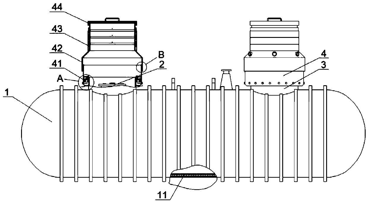
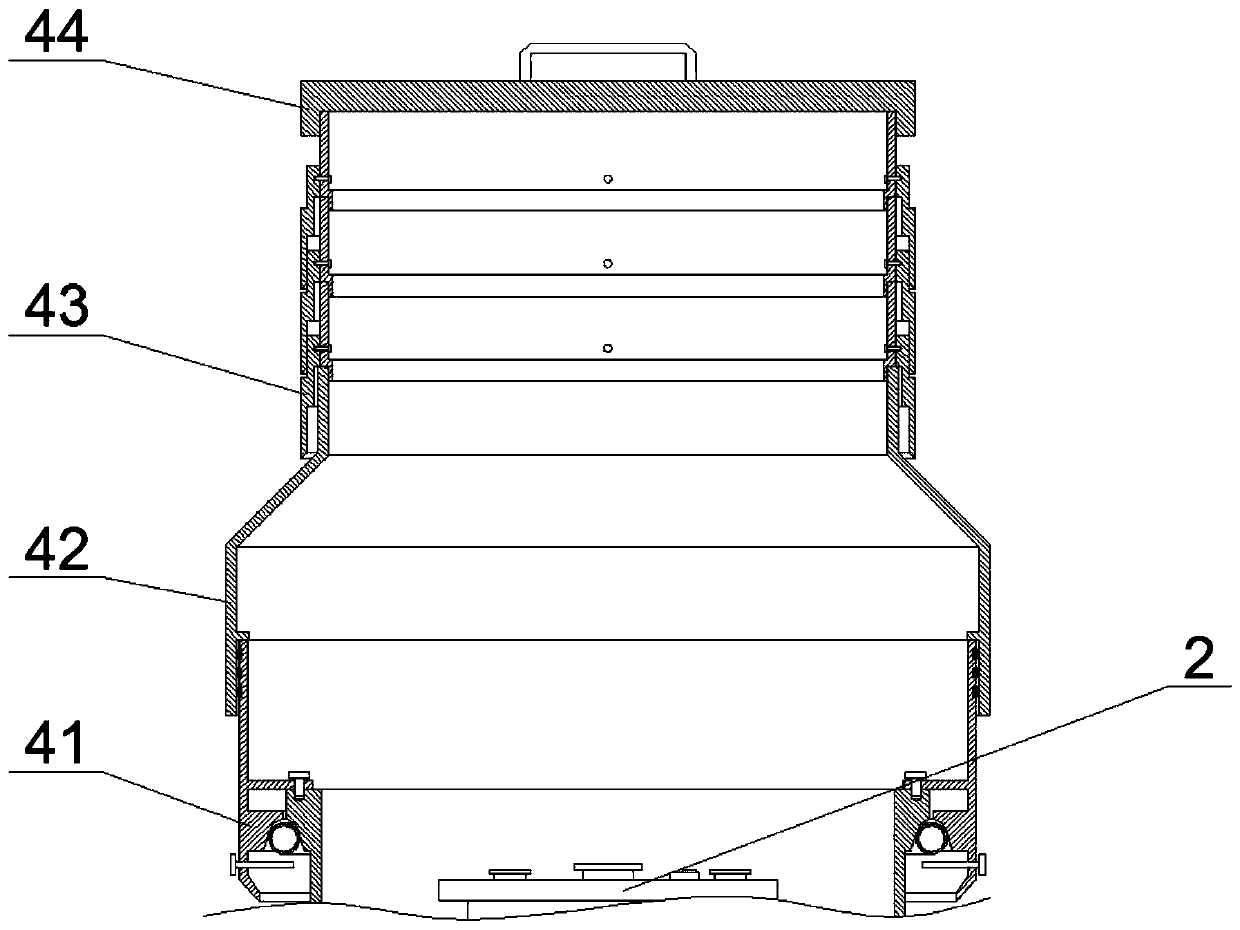
[0030] like Figure 1 to Figure 5As shown, the FF buried oil tank with an anti-seepage well seat provided in this embodiment includes a tank body 1 and two manholes 2 arranged on the tank body 1, and two manholes 2 are formed on the tank body 1 for wrapping Well block 3 covering two manholes 2. In this embodiment, in order to be able to monitor whether the inner tank body leaks in real time, the tank body 1 sequentially includes an inner resin-rich layer, an inner anti-seepage layer, a through-gap layer 11, an outer anti-seepage layer, and an outer rich resin layer from inside to outside. The resin layer, wherein the inner and outer resin-rich layers are made of noon glass fiber surface mat, the resin content should not be less than 90%, and the inner and outer anti-seepage layers are made of alkali-free glass fiber chopped strand mat or sprayed yarn, with a resin content of 65-75%. The through-gap layer 11 is filled with 3D fiberglass fabric material, mainly a composite of 3...


PUM


Abstract

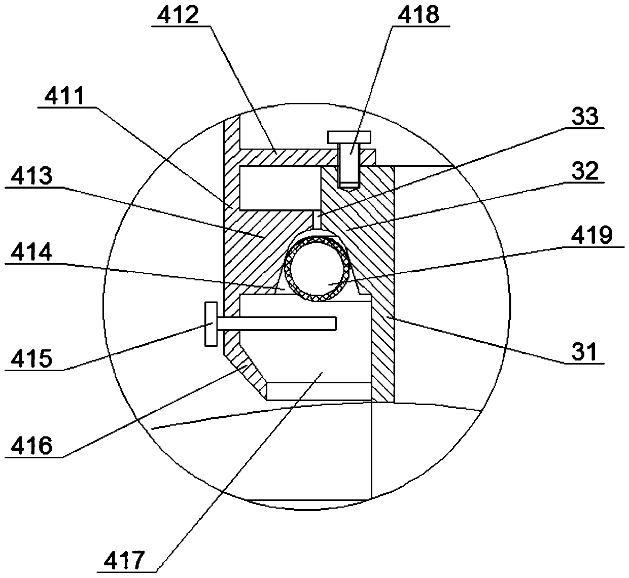
The invention discloses an FF buried oil tank with anti-seepage well bases. The FF buried oil tank comprises a tank body and the well bases arranged on the tank body. An anti-seepage assembly is arranged on each well base and comprises a barrel cover, an anti-solidification upper barrel, an anti-seepage middle barrel and an anti-seepage lower barrel, all of which are detachably connected in sequence from top to bottom. Each well base comprises a well base barrel and an inner press ring side formed on the outer edge of an upper port of the well base barrel. Each anti-seepage lower barrel comprises a lower barrel body and an outer press ring side formed in the lower barrel body. A first oblique angle is machined on the lower portion of the inner side of each outer press ring side, a second oblique angle is machined on the lower portion of the outer side of each inner press ring side, an annular cavity is formed between each first oblique angle and the corresponding second oblique angle,and a floating ring used for blocking the corresponding annular cavity is movably placed between each first oblique angle and the corresponding second oblique angle. The anti-seepage assemblies are arranged on the well bases, and therefore compared with a traditional sealing ring, the FF buried oil tank has the advantage that the waterproof effect is better, and the phenomenon that a great amountof accumulated water is generated in an operation well can be avoided.

Description

technical field [0001] The invention relates to the technical field of oil storage, in particular to an FF buried oil tank with an anti-seepage well seat. Background technique [0002] Double-layer glass fiber reinforced plastic oil tanks are also called FF buried oil tanks. The inner and outer layers are both glass fiber reinforced plastic tanks, which are superior to oil tanks with metal tanks in terms of internal and external corrosion resistance. During the burying of the FF buried oil tank, the well base and the part below the well base are backfilled with high-quality fine sand (without stones and harmful organic matter), and the part above the well base is solidified with concrete as the ground support. In the existing FF buried oil tank well base, the operation well and the well base are mostly connected by flanges, which are mainly used to prevent fine sand from entering the operation well and affecting the later maintenance and repair operations, but this structure...

Claims


Application Information

Patent Timeline
Patent Type & Authority Applications(China)
IPC IPC(8): B65D88/76B65D90/10
CPCB65D88/76B65D90/10Y02A20/00
Inventor 周瑛滨
Owner SICHUAN XINLEI BUILDING ENG CO LTD
Learn More