Lifting conveying equipment for electric power well maintenance

A technology of lifting and conveying and power wells, applied in the direction of lifting devices, etc., can solve problems such as accidents, stepping on the soles of the feet, easy slipping of hands, etc., and achieve the effect of reducing the probability of accidents and improving stability

Pending Publication Date: 2020-08-07
冯晓红
View PDF0 Cites 0 Cited by
  • Summary
  • Abstract
  • Description
  • Claims
  • Application Information

AI Technical Summary

Problems solved by technology

[0003] However, most of the existing power well maintenance personnel enter the power well through equipment such as rope ladders or straight ladders, which makes the maintenance process time-consuming and laborious, and it is easy to slip hands or step on the soles of the feet when climbing, resulting in accidents

Method used


Image

  • Lifting conveying equipment for electric power well maintenance
  • Lifting conveying equipment for electric power well maintenance
  • Lifting conveying equipment for electric power well maintenance

Examples


Embodiment Construction

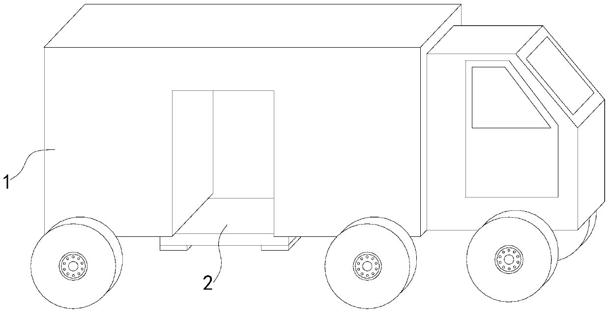
[0029] see Figures 1 to 9 , a schematic diagram of a planar structure and a schematic diagram of a three-dimensional structure of a lifting and conveying equipment for electric well maintenance.

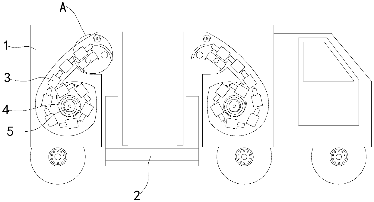
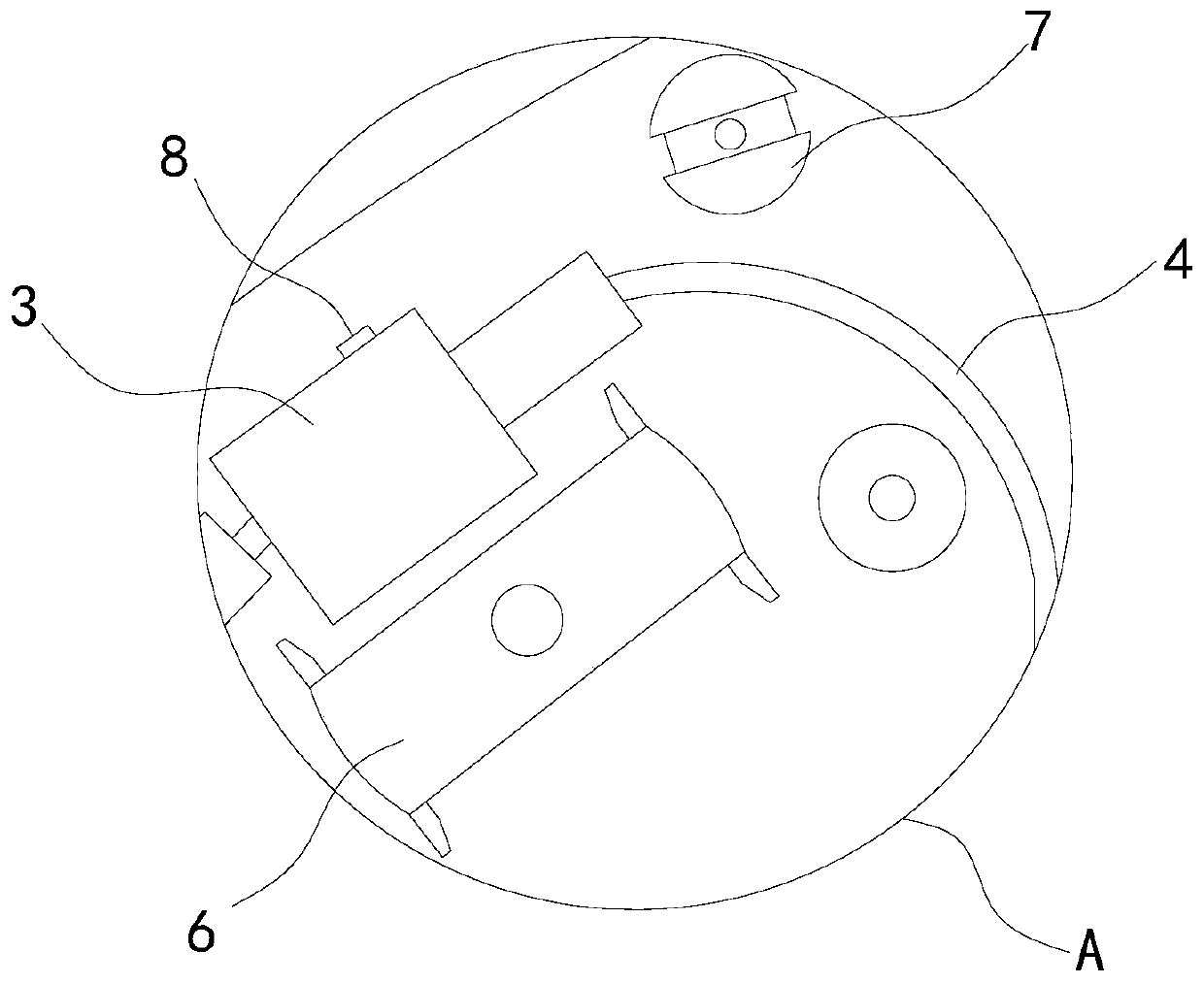
[0030] A lifting and conveying equipment for power well maintenance, comprising a device main body 1, a lifting platform 2 is movably installed at the lower end of the device main body 1, a connecting rope 4 is fixedly installed on both sides of the lifting platform 2, and a stabilizing block 3 is movably installed on the outside of the connecting rope 4.

[0031] In a specific implementation, a sheave 5 is fixedly installed inside the device main body 1, and the connecting rope 4 is fixedly connected to the outside of the sheave 5, so that the sheave 2 can be used to rotate and control the distance that the connecting rope 4 moves outward, thereby controlling the lifting platform 2. Move up and down to facilitate maintenance personnel to enter and leave the power well.

[0032] In...


PUM


Abstract

The invention relates to the field of electric power well maintenance equipment, in particular to lifting conveying equipment for electric power well maintenance. The lifting conveying equipment for electric power well maintenance comprises a device main body. A lifting table is movably mounted at the lower end in the device main body, connecting ropes are fixedly mounted on two sides of the lifting table, stabilizing blocks are movably mounted on the outer sides of the connecting ropes, a rope wheel is fixedly mounted in the device main body, and the connecting rope is fixedly connected to the outer side of the rope wheel, so that the rope wheel rotates to control the distance of the connecting rod moving outward so as to control the lifting table to move up and down. As the stabilizing blocks are movably connected to the outer side of the connecting rope in a sleeving manner and embedding blocks at the lower ends of the stabilizing blocks and embedding slots in the stabilizing blockscan be engaged to each other, when the stabilizing blocks are connected end to end on the outer side of the connecting rope, the device main body is attached to the inner wall and the outer sides ofthe stabilizing blocks, so that the lifting table which moves does not swing, and therefore, the moving stability of the lifting table is improved, and the probability that maintenance staff have accidents is reduced.

Description

technical field [0001] The invention relates to the field of electric well maintenance equipment, in particular to a lifting and conveying equipment for electric well maintenance. Background technique [0002] With the development of society, the laying of power lines is becoming more and more perfect. In the suburbs, the power lines are erected in the air through poles; Electric manhole covers, thus facilitating repairs in the event of a breakdown. [0003] However, most of the existing power well maintenance personnel enter the power well through equipment such as rope ladders or straight ladders, which makes the maintenance process time-consuming and laborious, and it is easy to slip hands or step on the soles of the feet when climbing, resulting in accidents. Contents of the invention [0004] The utility model relates to lifting and conveying equipment for electric well maintenance. The device can stably and conveniently send maintenance personnel into the interior o...

Claims


Application Information

Patent Timeline
Patent Type & Authority Applications(China)
IPC IPC(8): B66F11/04
CPCB66F11/04
Inventor 冯晓红
Owner 冯晓红
Why Eureka
Try Eureka