Bearing quenching device with rotating wheel type buffering structure

A technology of buffer structure and quenching device, applied in the direction of quenching device, heat treatment equipment, furnace, etc., can solve the problems of deformation of thin-walled ferrules, affecting product quality, etc., and achieve the effect of weakening impact force and avoiding collision deformation.

Active Publication Date: 2020-08-07
江苏立一新材料科技有限公司
View PDF9 Cites 1 Cited by
  • Summary
  • Abstract
  • Description
  • Claims
  • Application Information

AI Technical Summary

Problems solved by technology

[0002] The current heat treatment of bearing rings includes oil quenching, salt bath quenching, etc., and the oil quenching method generally installs an oil tank on the ground, and erects a horizontal conveyor chain belt on the upper side of one end of the oil tank. There is another horizontal conveyor chain belt, and one end of the other conveyor chain belt is provided with an oblique output chain belt, which enters the bearing ring through the conveyor chain belt on the upper side of the oil tank, and the bearing ring falls into the oil tank and falls on the On the conveyor chain belt in the oil tank, and then use the output chain belt to output the bearing; but for some thin-walled bearings, because the output bearing ring from the conveyor chain belt falls into the oil tank at the same point, and at the same time, between the conveyor chain belt inside and outside the oil tank The distance between the thin-walled ferrules is large, and when the thin-walled ferrules fall, there will be a certain impact force, and there will be bumps between the thin-walled ferrules, which will cause the thin-walled ferrules to deform and affect the quality of the product.

Method used


Image

  • Bearing quenching device with rotating wheel type buffering structure
  • Bearing quenching device with rotating wheel type buffering structure
  • Bearing quenching device with rotating wheel type buffering structure

Examples


Embodiment Construction

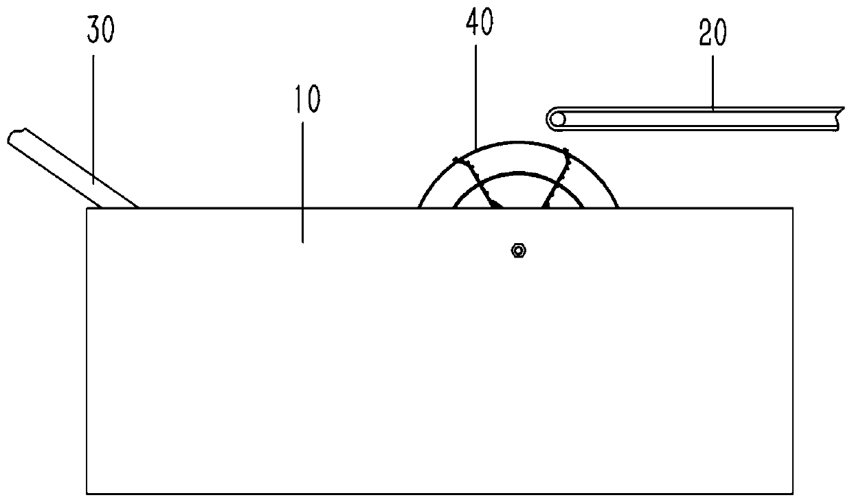
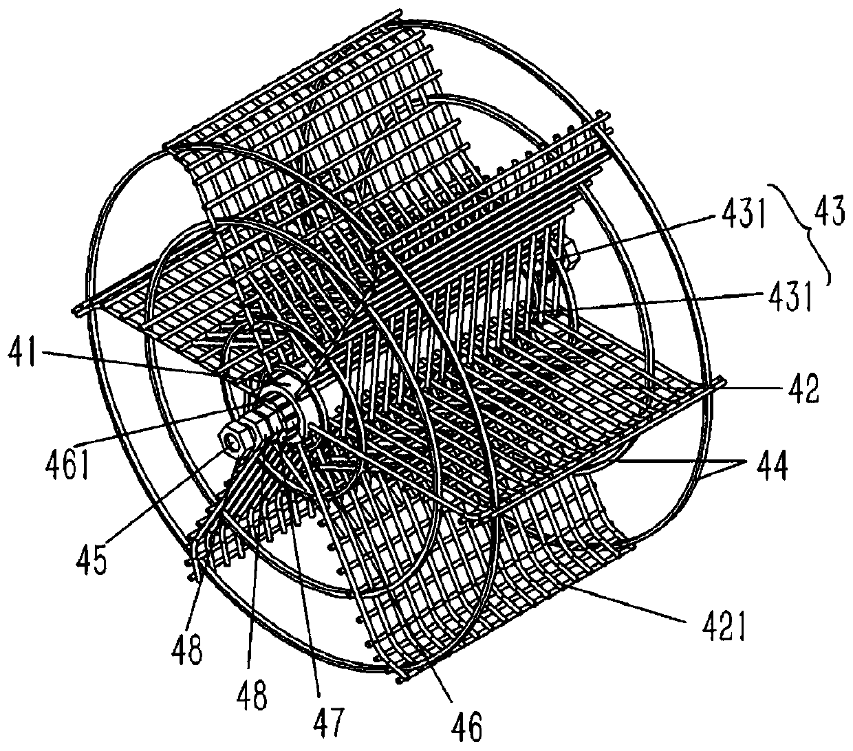
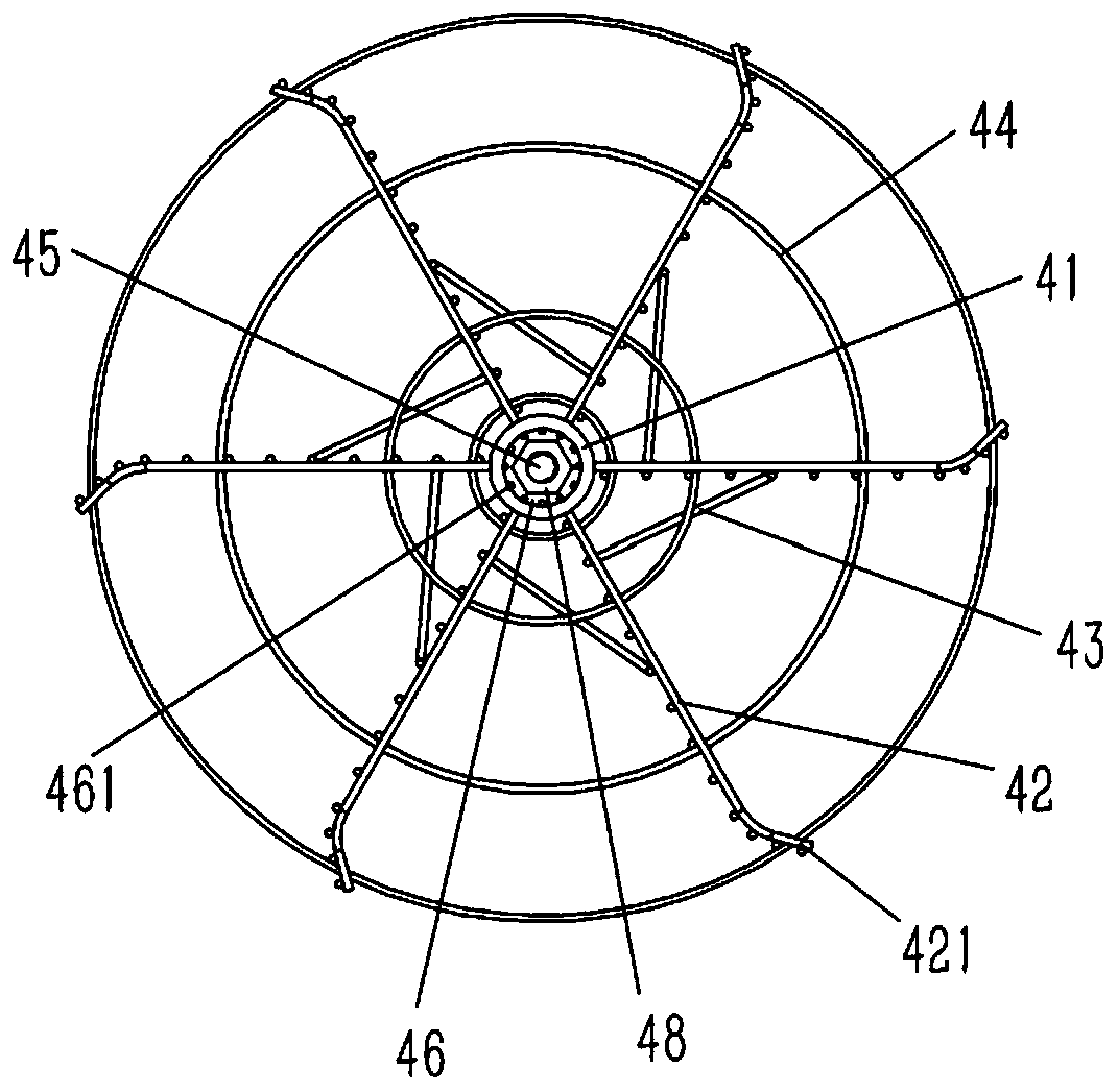
[0019] Example: see Figures 1 to 4 As shown, a bearing quenching device with a wheel-type buffer structure includes a quenching oil tank 10, a horizontal input chain belt 20 is provided above one end of the quenching oil tank 10, and an oblique output chain belt is inserted at the other end of the quenching oil tank 10. 30. A buffer impeller 40 is inserted in the quenching oil tank 10 directly below the output end of the input chain belt 20. The buffer impeller 40 includes a shaft sleeve 41, and a rotating shaft 45 is inserted into the shaft sleeve 41. The two ends of the rotating shaft 45 are plugged and fixed in the quenching oil tank 10. on the side wall; the outer wall of the bushing 41 is fixed with a number of steel mesh buffer blades 42, and the outer side of the buffer blade 42 is bent to form an upwardly inclined deflector 421, and the two buffer blades 42 Several rings of reinforcement rings 44 are fixed on the sides; inclined ribs 43 are fixed between adjacent buff...


PUM


Abstract

The invention discloses a bearing quenching device with a rotating wheel type buffering structure, and the device comprises a quenching oil groove, a horizontal input chain belt is arranged above oneend of the quenching oil groove, an output chain belt is inserted and arranged aslant at the other end of the quenching oil groove, a buffering vane wheel is inserted in the quenching oil groove directly below an output end of the input chain belt, the buffering vane wheel comprises a shaft sleeve, a rotating shaft is inserted and connected in the shaft sleeve, and two ends of the rotating shaft are inserted and connected fixedly on a side wall of the quenching oil groove; an external wall of the shaft sleeve is fixedly provided with several buffering vanes in the shape of a steel wire gauze,external side edges of the buffering vanes are bended to form guide plates leaning upwards, and several reinforcing rings are fixed at two side edges of the buffering vanes; a rib plate is arranged aslant between neighboring buffering vanes, and the rib plate is composed of several parallel ribs.

Description

technical field [0001] The invention relates to the technical field of bearing heat treatment devices, in particular to a bearing quenching device with a wheel type buffer structure. Background technique [0002] The current heat treatment of bearing rings includes oil quenching, salt bath quenching, etc., and the oil quenching method generally installs an oil tank on the ground, and erects a horizontal conveyor chain belt on the upper side of one end of the oil tank. There is another horizontal conveyor chain belt, and one end of the other conveyor chain belt is provided with an oblique output chain belt, which enters the bearing ring through the conveyor chain belt on the upper side of the oil tank, and the bearing ring falls into the oil tank and falls on the On the conveyor chain belt in the oil tank, and then use the output chain belt to output the bearing; but for some thin-walled bearings, because the output bearing ring from the conveyor chain belt falls into the oil...

Claims


Application Information

Patent Timeline
Patent Type & Authority Applications(China)
IPC IPC(8): C21D1/63C21D9/40
CPCC21D1/63C21D9/0062C21D9/40
Inventor 黄杰
Owner 江苏立一新材料科技有限公司
Why Eureka
Try Eureka