
Water pump bearing with double-row balls

A technology of water pump shaft and double row ball, applied in the direction of shaft and bearing, bearing, bearing components, etc., can solve the problems of unfavorable product promotion and use, increase product use cost, unfavorable maintenance and replacement, etc., to ensure smooth operation and guaranteed use effect. , the effect of simple structure

Active Publication Date: 2020-08-07
C&U CO LTD +2
View PDF6 Cites 0 Cited by
  • Summary
  • Abstract
  • Description
  • Claims
  • Application Information

AI Technical Summary

Problems solved by technology

The existing shaft-connected bearings of water pumps generally have a double-row structure. When the load is relatively small, the double-row ball structure can meet the requirements. When the force on the pulley end is large, cylindrical rollers can be used at the pulley end. , in order to increase the load-bearing capacity, and the impeller end is not changed, and the ball structure is adopted, which is a double-row structure with one column and one ball, but the price of cylindrical rollers is compared with the cost of raceway processing. Steel ball structure is used The more expensive ones require higher machining accuracy, which increases the production and processing costs of enterprises, and is not conducive to the promotion and use of products. However, the simple use of double balls, the steel balls at the pulley end are subject to greater bearing capacity and greater wear and tear. Affects the service life, is not conducive to maintenance and replacement, and increases the cost of product use

Method used


Image

  • Water pump bearing with double-row balls
  • Water pump bearing with double-row balls
  • Water pump bearing with double-row balls

Examples


Embodiment Construction

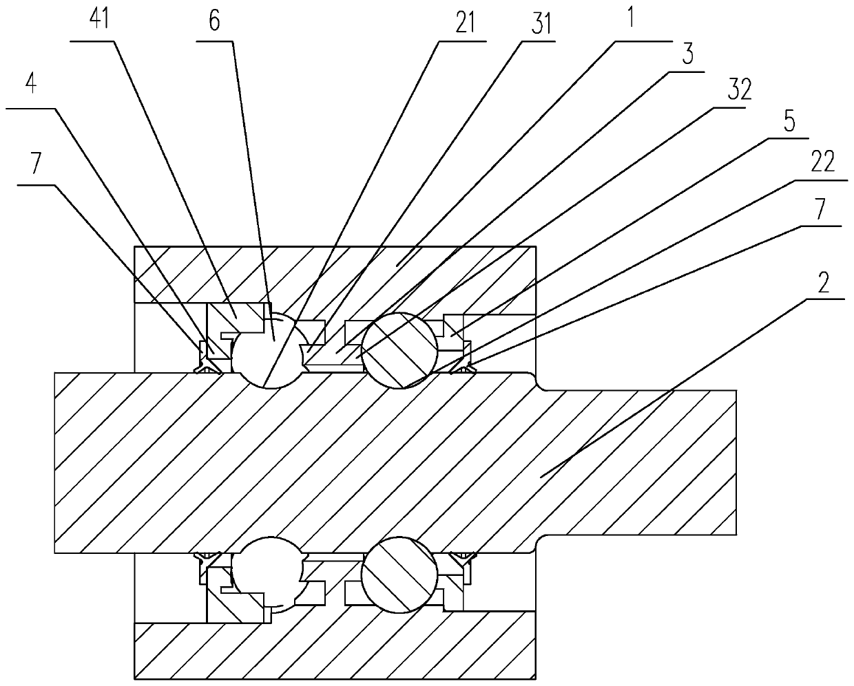
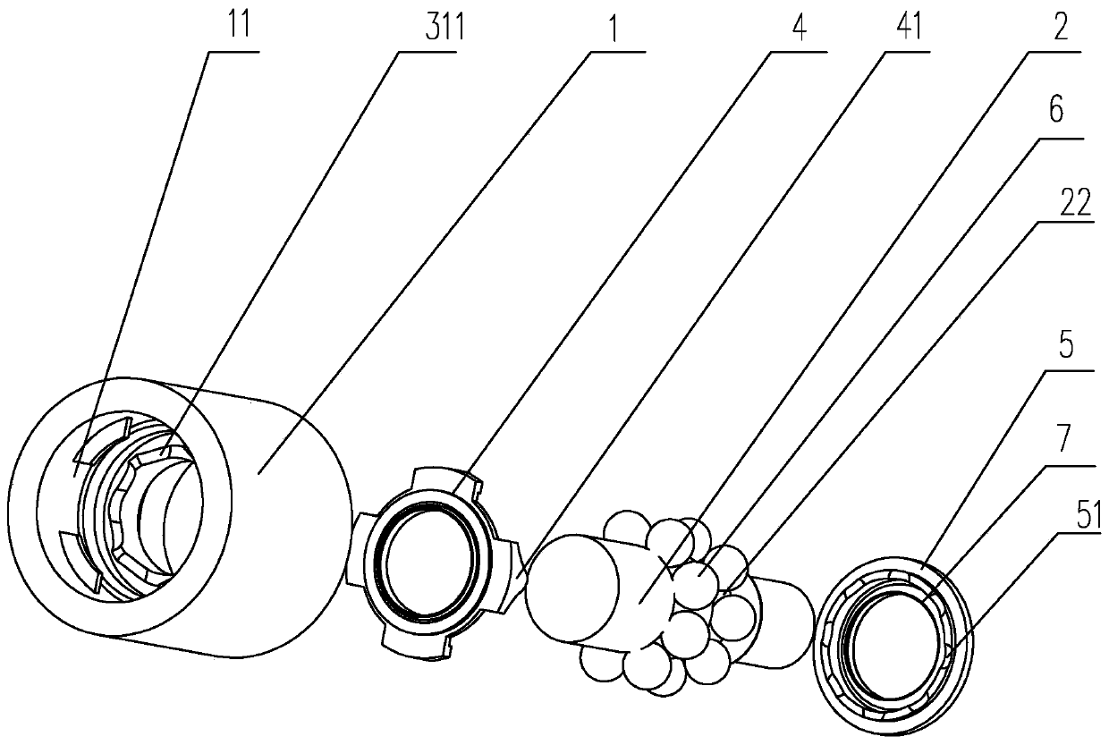
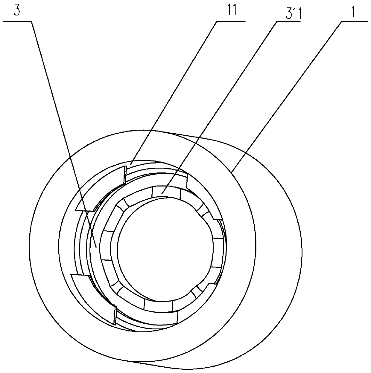
[0017] Embodiments of the shaft-connected bearing of the double-row ball water pump of the present invention are for example Figure 1-2 Shown: including the outer ring 1 and the mandrel 2, a first raceway groove 21 and a second raceway groove 22 are formed between the outer ring 1 and the mandrel 2, and the first raceway groove 21 is close to the mandrel 2 The pulley end is set, the second raceway groove 22 is set close to the impeller end, the first raceway groove 21 and the second raceway groove 22 are provided with rolling steel balls 6, and the inner wall of the outer ring 1 is on the A positioning frame 3 is arranged between the first raceway groove 21 and the second raceway groove 22. The cross section of the positioning frame 3 is T-shaped. The positioning frame 3 includes a base and first positioning protrusions arranged on both sides of the base edge 31 and a second positioning flange 32, the first positioning flange 31 is arranged close to the first raceway groove 2...


PUM


Abstract

The invention discloses a water pump bearing with double-row balls. The water pump bearing comprises an outer ring and a mandrel, roller path grooves are formed between the outer ring and the mandrel,steel balls are arranged in the roller path grooves in a rolling mode, a positioning frame is arranged at a position, between the two roller path grooves, of the inner wall of the outer ring, the section of the positioning frame is arranged in a T shape, the positioning frame comprises a base, a first positioning flange and a second positioning flange, positioning grooves are formed in the firstpositioning flange at intervals, positioning ring grooves are formed in the second positioning flange, ball containing grooves are formed in the positions, corresponding to the roller path grooves, ofthe outer ring, the ball containing grooves communicate with the roller path grooves, the ball containing grooves are formed in the middle positions of the positioning grooves, a first retaining sideframe and a second retaining side frame are further clamped to the two sides of the outer ring, a positioning protrusion is arranged on the first retaining side frame in an extending manner, arc-shaped grooves are formed in the two sides of the end of the positioning protrusion, and retaining grooves are formed in the second retaining side frame at intervals. According to the water pump bearing with the double-row balls, the structure is simple, machining is easy, and meanwhile two modes can be adopted so that the using requirements of high loads and conventional loads can be met.

Description

technical field [0001] The invention relates to the technical field of bearings, in particular to a shaft-connected bearing of a double-row ball water pump. Background technique [0002] The shaft-connected bearing of the water pump is the core of the mechanical engine, which includes the shaft core, outer ring, cage and rollers; the outer ring is generally fixed on the water pump housing and does not rotate; one end of the shaft core protrudes from the outer ring and is connected to the impeller; The other end of the shaft core is connected with a pulley shaft, and the pulley shaft is connected with the pulley to transmit power to the impeller. The existing shaft-connected bearings of water pumps generally have a double-row structure. When the load is relatively small, the structure of double-row balls can meet the requirements. When the force on the pulley end is large, cylindrical rollers can be used at the pulley end. , in order to increase the load-bearing capacity, an...

Claims


Application Information

Patent Timeline
IPC IPC(8): F16C19/18F16C33/38F16C33/40F16C33/58F04D29/046
CPCF04D29/046F16C19/18F16C33/3818F16C33/40F16C33/583
Inventor 李伯建
Owner C&U CO LTD
Learn More