
Manufacturing method of ultra-thin VC

An ultra-thin, ultrasonic technology, applied in the direction of manufacturing tools, lighting and heating equipment, indirect heat exchangers, etc., can solve the problems of scrapped raw materials, failure to use normally, low welding fastness, etc., to avoid waste and overcome spatter and oxidation, quality improvement effect

Pending Publication Date: 2020-08-07
江苏明利嘉科技有限公司
View PDF1 Cites 1 Cited by
  • Summary
  • Abstract
  • Description
  • Claims
  • Application Information

AI Technical Summary

Problems solved by technology

[0005] Aiming at the deficiencies of the prior art, the present invention provides a manufacturing method of ultra-thin VC, which has the advantages of repeated welding and guaranteed production quality, and solves the problem that traditional ultra-thin VC will be processed by brazing. For sintering, only the corners are welded when welding, and the fastness of welding is low. If the welding quality is not good after welding twice, the raw materials will be directly scrapped and cannot be used normally.

Method used


Image

  • Manufacturing method of ultra-thin VC
  • Manufacturing method of ultra-thin VC
  • Manufacturing method of ultra-thin VC

Examples


Embodiment 1

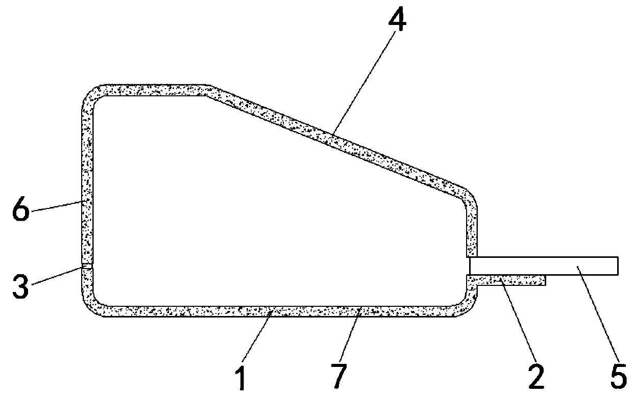
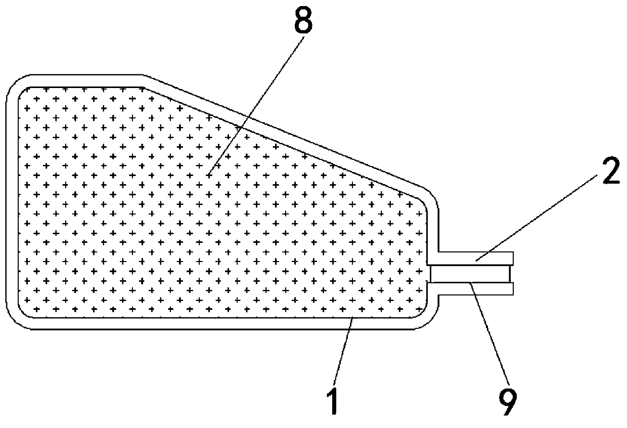
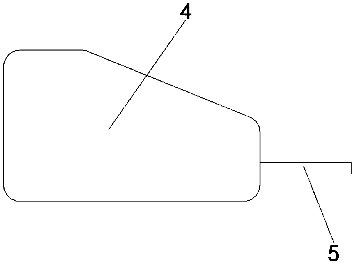
[0027] Embodiment 1: An ultra-thin VC, including a lower cover plate 1, a mounting plate 2 is fixedly installed on the right side of the lower cover plate 1, an upper cover plate 4 is fixedly installed on the top of the lower cover plate 1, and the lower cover plate 1 and The upper cover plates 4 are connected to each other to form an accommodating space, the lower cover plate 1 and the upper cover plate 4 have the same length, the left side of the connection between the lower cover plate 1 and the upper cover plate 4 is provided with a welding groove 3, and the upper cover plate 4 The liquid inlet pipe 5 is fixedly installed on the right side, and the wool layer 6 is fixedly installed inside the lower cover plate 1 and the upper cover plate 4. The capillary layer 6 is a copper mesh that is horizontally and vertically alternated, and the copper mesh is braided by multiple copper wires. Formed, the top of the lower cover plate 1 and the bottom of the upper cover plate 4 are prov...

Embodiment 2

[0034] Embodiment 2: An ultra-thin VC, including a lower cover plate 1, a mounting plate 2 is fixedly installed on the right side of the lower cover plate 1, an upper cover plate 4 is fixedly installed on the top of the lower cover plate 1, and the lower cover plate 1 and The upper cover plates 4 are connected to each other to form an accommodating space, the lower cover plate 1 and the upper cover plate 4 have the same length, the left side of the connection between the lower cover plate 1 and the upper cover plate 4 is provided with a welding groove 3, and the upper cover plate 4 The liquid inlet pipe 5 is fixedly installed on the right side, and the wool layer 6 is fixedly installed inside the lower cover plate 1 and the upper cover plate 4. The capillary layer 6 is a copper mesh that is horizontally and vertically alternated, and the copper mesh is braided by multiple copper wires. Formed, the top of the lower cover plate 1 and the bottom of the upper cover plate 4 are prov...


PUM


Abstract

The invention relates to the technical field of vapor chambers, and discloses an ultra-thin VC. The ultra-thin VC comprises a lower cover plate. A mounting plate is fixedly mounted on the right side of the lower cover plate. The top of the lower cover plate is fixedly provided with an upper cover plate. A welding groove is formed in the left side of a joint of the lower cover plate and the upper cover plate. A liquid inlet pipe is fixedly mounted on the right side of the upper cover plate. Wool layers are fixedly mounted inside the lower cover plate and the upper cover plate. Grooves are formed in the top of the lower cover plate and the bottom of the upper cover plate. An etching layer is arranged on the inner bottom wall of the lower cover plate. A mounting groove is formed in the top ofthe mounting plate. According to a manufacturing method of the ultra-thin VC, ultrasonic metal welding is adopted, so that the quality of ultrasonic wave metal welding production is effectively improved, waste of raw materials is avoided, and the ultra-thin VC does not need to be welded little by little. The ultra-thin VC is sealed in a circle through ultrasonic wave metal welding and welding, sothat the excellence rate of ultra-thin VC production is guaranteed.

Description

technical field [0001] The invention relates to the technical field of temperature chambers, in particular to a manufacturing method of ultra-thin VC. Background technique [0002] The vapor chamber is a vacuum chamber vapor chamber. The technology is similar to the heat pipe in principle, but it is different in the conduction mode. The heat pipe is a one-dimensional linear heat conduction, while the heat in the vacuum chamber vapor chamber is in a two-dimensional Surface conduction, so more efficient. [0003] According to the manufacturing method of the chamber and the chamber proposed by the Chinese authorized invention CN201710808692.6, the beneficial effect is that the manufacturing of the chamber is realized by processing the core material and embedding it in the cavity, which avoids problems such as high-temperature sintering and reduces Reduce energy consumption and cost, improve the performance of the vapor chamber, but the traditional ultra-thin VC will be sintere...

Claims


Application Information

Patent Timeline
Patent Type & Authority Applications(China)
IPC IPC(8): F28D15/04B23K20/10
CPCF28D15/04B23K20/10
Inventor 陈彬彬
Owner 江苏明利嘉科技有限公司
Learn More