Fully-polarized radar life detection and positioning method
A life detection and positioning method technology, applied in measurement devices, radio wave measurement systems, radio wave reflection/re-radiation, etc. problem, to achieve the effect of simple principle, enhanced target echo, and easy operation
- Summary
- Abstract
- Description
- Claims
- Application Information
AI Technical Summary
Problems solved by technology
Method used
Image
Examples
Embodiment 1
[0038] Embodiment 1: as figure 1 Shown, a kind of fully polarized radar life detection positioning method of the present invention, it comprises:
[0039] Step S1: The monostatic radar uses an all-polarization microstrip antenna as a transmitting antenna and a receiving antenna; full-polarization detection is realized on the hardware side.
[0040] Step S2: When the monostatic radar is working, use the fully polarized transmitting antenna to transmit electromagnetic waves to detect the measured area;
[0041] Step S3: using the fully polarized receiving antenna to receive the scattering waveform of the target;
[0042] Step S4: Perform preprocessing on the received signal in step S3, calculate the polarization scattering matrix, invert and estimate the time delay, and finally obtain the target information.
[0043] After adopting the above method, the present invention increases the echo intensity of the detection target and improves the detection probability of the life det...
Embodiment 2
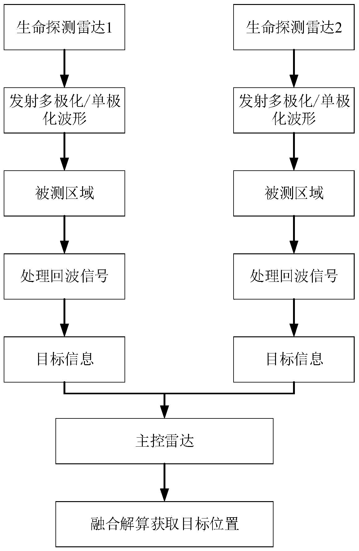
[0044] Embodiment 2: as figure 2 As shown, the present invention uses two or more life detection radars to combine and deploy a network for life detection. That is, a distributed radar is composed of more than two life detection radars equipped with fully polarized microstrip antennas and a main control radar, and the fully polarized transmitting antenna is used to emit electromagnetic waves to detect the measured area.
[0045] During the working process of the distributed radar, each life detection radar will emit a multi-polarization waveform or a single-polarization waveform to detect the detected area.
[0046] During the working process of the distributed radar, each life detection radar uses a fully polarized receiving antenna to receive signals.
[0047] After each life detection radar receives the signal, each life detection radar processes the echo signal to obtain target information.
[0048] Finally, the obtained target information is transmitted to the main con...
Embodiment 3
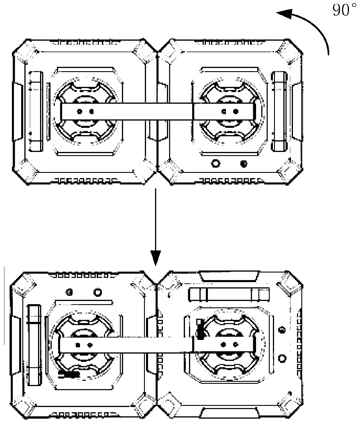
[0049] Embodiment 3: as image 3As shown, in this example, the present invention takes two assembly single-polarization antenna life detection radars as an example to form a distributed radar, that is, when two assembly single-polarization antenna life detection radars form a distributed radar to work, one of them The life detection radar equipped with a single-polarization antenna is rotated by 90°, so that the polarization directions of electromagnetic waves emitted by two life detection radars equipped with a single-polarization antenna are orthogonal to each other. Each life detection radar equipped with a single-polarization antenna receives the waveform emitted by itself and performs target detection, achieving the effect of multi-polarization antenna detection targets. Extending this type of working mode to the joint work of multiple single-polarization radars, each radar rotates at different angles, so that the polarization directions of the electromagnetic waves emitt...
PUM
 Abstract
Description
Claims
Application Information
 - R&D
- Intellectual Property
- Life Sciences
- Materials
- Tech Scout
- Unparalleled Data Quality
- Higher Quality Content
- 60% Fewer Hallucinations
Browse by: Latest US Patents, China's latest patents, Technical Efficacy Thesaurus, Application Domain, Technology Topic, Popular Technical Reports.
© 2025 PatSnap. All rights reserved.Legal|Privacy policy|Modern Slavery Act Transparency Statement|Sitemap|About US| Contact US: help@patsnap.com


