
Power module terminal

A power module terminal and end face technology, which is applied in the direction of welding/welding connection, etc., can solve the problems of low terminal strength and low vibration resistance, and achieve high structural rigidity, good vibration resistance, and not easy to deform.

Active Publication Date: 2020-08-07
湖南国芯半导体科技有限公司
View PDF12 Cites 0 Cited by
  • Summary
  • Abstract
  • Description
  • Claims
  • Application Information

AI Technical Summary

Problems solved by technology

However, the power module terminals currently used have problems such as weak anti-vibration ability and low terminal strength.

Method used


Image

  • Power module terminal
  • Power module terminal
  • Power module terminal

Examples


Embodiment 1

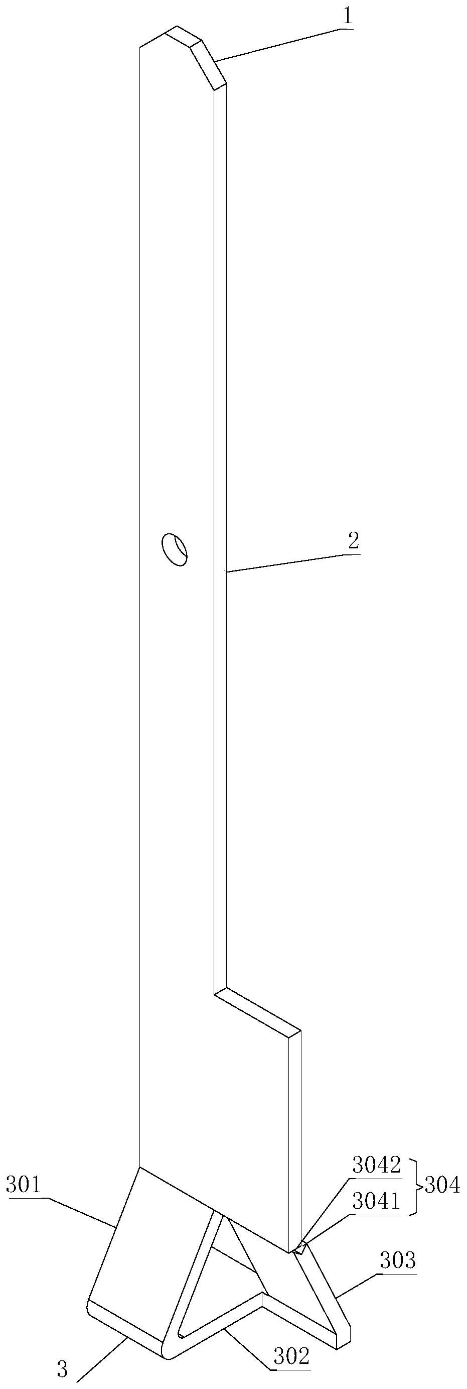
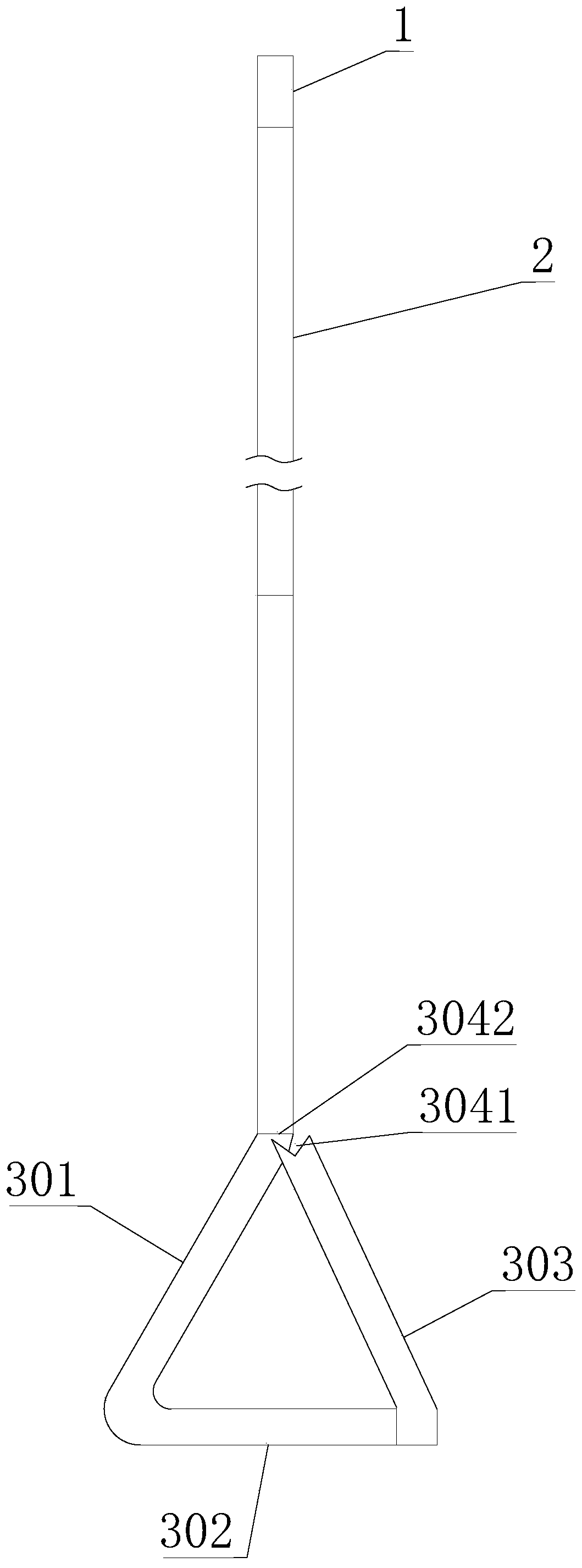
[0029] Such as Figure 1 to Figure 3 As shown, the power module terminal of this embodiment includes a head 1, a middle portion 2, and a welding structure 3 that are sequentially connected; the welding structure 3 includes a support portion 301, a buffer portion 303, and a welding portion 302. One end of the support portion 301 and The middle part 2 is connected, the other end is connected to one end of the welding part 302, the other end of the welding part 302 is connected to one end of the buffer part 303, and a stop structure 304 is provided between the other end of the buffer part 303 and the middle part 2, namely An opening is formed between the buffer portion 303 and the middle portion 2; the supporting portion 301, the buffer portion 303 and the welding portion 302 of the welding structure 3 are triangular in shape as a whole. When the terminal head 1 is pressed, the head 1 and the middle part 2 will be compressed to the welding structure 3 side. Since an opening is form...

Embodiment 2

[0035] Such as Figure 4~6 As shown, the difference between this embodiment and the first embodiment is only the difference in the stop structure 304. In this embodiment, the stop structure 304 includes a stop surface 3042, and the stop surface 3042 is located at the end of the middle part 2. A limit step 3043 is formed between the mouth surface 3042 and the middle portion 2, and the stop surface 3042 is matched with the end surface of the other end of the buffer portion 303. Similarly, when the terminal head 1 is pressed, the end portion of the buffer portion 303 is It is attached to the stop surface 3042 to maximize the contact area and ensure the reliability of compression resistance. At the same time, the limit step 3043 ensures the limit deformation distance. Of course, the stop surface 3042 can also be located at the end of the buffer portion 303, a limit step 3043 is formed between the stop surface 3042 and the buffer portion 303, and the stop surface 3042 is matched wit...


PUM


Abstract

The invention discloses a power module terminal, which comprises a head part, a middle part and a welding structure which are sequentially connected, wherein the welding structure comprises a supporting part, a buffering part and a welding part, one end of the supporting part is connected with the middle part, the other end of the supporting part is connected with one end of the welding part, theother end of the welding part is connected with one end of the buffering part, a seam allowance structure is arranged between the other end of the buffering part and the middle part, and the supporting part, the buffering part and the welding part of the welding structure are integrally triangular. The power module terminal has the advantages of being simple in structure, good in vibration resistance, high in welding strength, good in through-flow capacity and the like.

Description

Technical field [0001] The present invention mainly relates to the field of power module manufacturing, in particular to a power module terminal. Background technique [0002] A variety of terminals are used in power modules. The terminals can be integrated with the housing and connected to the chip by bonding wires or ultrasonic welding. It can also be used as a separate terminal to be welded to the module to be electrically connected to the chip chip. connection. Among them, the individual terminals can be more flexibly arranged around the chip, so that the inductance of the module is reduced, so it has been widely used. However, the power module terminals currently used have problems such as weak anti-vibration ability and low terminal strength. Summary of the invention [0003] The technical problem to be solved by the present invention lies in: in view of the technical problems existing in the prior art, the present invention provides a power module terminal with simple str...

Claims


Application Information

Patent Timeline
Patent Type & Authority Applications(China)
IPC IPC(8): H01R4/02
CPCH01R4/02
Inventor 柯攀齐放戴小平曾亮姚亮刘洋
Owner 湖南国芯半导体科技有限公司
Learn More