
Camera module and motor thereof

A camera module and motor technology, applied in the field of cameras, can solve the problems of large module size, affecting the screen ratio of small electronic devices, and screen size reduction, etc. Effect

Pending Publication Date: 2020-08-07
KUNSHAN Q TECH CO LTD
View PDF0 Cites 2 Cited by
  • Summary
  • Abstract
  • Description
  • Claims
  • Application Information

AI Technical Summary

Problems solved by technology

[0003] However, due to too many components in the existing camera module, the size of the module is too large, and the size of the module is too large to relatively reduce the screen size of the small electronic device, thereby affecting the screen ratio of the screen of the small electronic device

Method used


Image

  • Camera module and motor thereof
  • Camera module and motor thereof

Examples


Embodiment 1

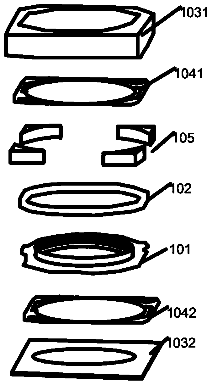
[0034] Embodiment 1 of the present invention provides a motor of a camera module, which is used to drive the movement of the lens to achieve the purpose of focusing, and can be applied to small electronic devices, such as mobile phones, tablets, and smart watches.

[0035] Such as figure 1 As shown, the motor of the camera module includes: a motor carrier 101, which is used to carry a multi-layer lens; a coil 102, which is sleeved outside the motor carrier; , the other end is fixed inside the casing; the magnet 105 surrounds the coil 102 and is fixed inside the casing 103, the magnet 105 is used to generate a magnetic field; wherein, when the coil 102 is energized, the coil 102 can Under the action of the magnetic field, it moves perpendicular to the direction of the magnetic field to achieve the purpose of focusing.

[0036] Since the motor is equipped with a motor carrier 101, the motor carrier 101 directly carries the lens, and the existing lens barrel structure for carryi...

Embodiment 2

[0049] Based on the same inventive concept, an embodiment of the present invention also provides a camera module, which is applied to small electronic devices, such as mobile phones, tablets, and smart watches.

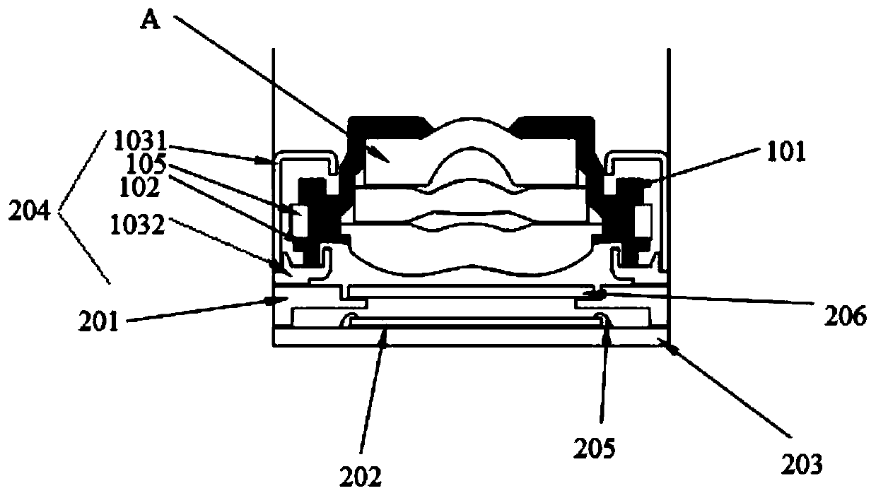
[0050] Such as figure 2As shown, the camera module includes: a bracket 201, a photosensitive chip 202, a circuit substrate 203, and any of the above-mentioned motors 204; The bottom of the bracket 201 is adhered to the circuit substrate 203 . These adhesions are fixed by glue adhesion in particular.

[0051] The motor 204 includes: a motor carrier 101, which is used to carry a multi-layer lens A; a coil 102, which is sleeved outside the motor carrier 101; a casing, which is sleeved outside the coil 102; a supporting elastic piece, one end of which is connected to the motor Carrier 101, the other end of which is fixed inside the housing; magnet 105, which surrounds the coil 102 and is fixed inside the housing for generating a magnetic field; electrifying the coil 10...


PUM


Abstract

The invention relates to the technical field of cameras, in particular to a camera module and a motor thereof. The motor comprising a motor carrier, a coil, an outer shell, a supporting elastic sheetand magnets, wherein the motor carrier is used for bearing multiple layers of lenses; the coil is arranged outside the motor carrier in a sleeving manner; the outer shell is arranged outside the coilin a sleeving manner; one end of the supporting elastic sheet is connected with the motor carrier, and the other end of the supporting elastic sheet is fixed in the outer shell; the magnets surround the coil, are fixed on the inner side of the outer shell and are used for generating a magnetic field. When the coil is powered on, the coil can move in the direction perpendicular to the magnetic field under the action of the magnetic field of the magnets, so as to achieve the focusing purpose, further, a lens barrel of lenses in the prior art is abandoned, the size of the motor of the camera module is effectively reduced, namely, the size of the camera module is reduced, enough space is reserved for accommodating other assemblies, and the performance of all device structures is guaranteed while the size of small equipment is reduced.

Description

technical field [0001] The invention relates to the technical field of cameras, in particular to a camera module and a motor thereof. Background technique [0002] The existing camera module uses a lens and a motor. By connecting the lens and the carrier of the motor through a threaded structure, the carrier of the motor can push the lens to move up and down so that the lens can reach the clearest imaging position and complete automatic adjustment. Focus action. [0003] However, due to too many components in the existing camera module, the size of the module is too large, and the size of the module is too large to relatively reduce the screen size of the small electronic device, thereby affecting the screen ratio of the screen of the small electronic device. The screen-to-body ratio of the screen of the small electronic device is an important parameter that affects the appearance of the small electronic device. [0004] Therefore, how to reduce the size of the camera modu...

Claims


Application Information

Patent Timeline
Patent Type & Authority Applications(China)
IPC IPC(8): H04N5/225
CPCH04N23/55H04N23/51
Inventor 邹兵陈亮
Owner KUNSHAN Q TECH CO LTD
Learn More