
A composite insulating reflective layer

A technology of composite insulating and reflective layers, applied in the direction of semiconductor devices, electrical components, circuits, etc., can solve the problems of easy peeling, chipping film and film roughness, film chipping or peeling, etc., to improve chipping and peeling phenomenon. , The effect of improving the interlayer stress problem of the film

Active Publication Date: 2022-03-29
XIAMEN SANAN OPTOELECTRONICS CO LTD
View PDF16 Cites 0 Cited by
  • Summary
  • Abstract
  • Description
  • Claims
  • Application Information

AI Technical Summary

Problems solved by technology

[0002] The existing distributed Bragg reflector (hereinafter referred to as: DBR) structure is made of periodic stacking of low refractive index and high refractive index materials, and the common low refractive index material is SiO 2 , high refractive index material is TiO 2 ; Usually the medium A / medium B that makes up the DBR can be any film or air, the old SiO 2 / TiO 2 The growth stress of the stacked film layer is relatively large, which is prone to cracking or peeling off of the film layer
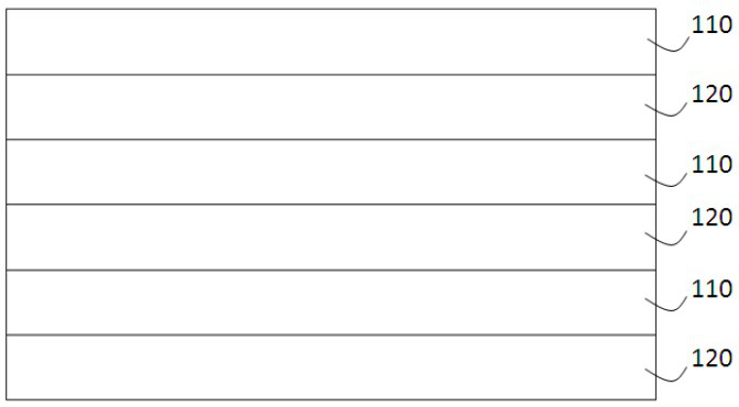
[0003] see figure 1 , the existing DBR structure filling is a periodic stacking combination of two media with a large difference in refractive index, for example, the first material layer 110 and the second material layer 120 are stacked on each other, and the first material layer 110 and the second material layer The material of 120 includes SiO 2 、TiO 2 , Nb 2 o 5 or Ta 2 o 5 Etc. Coating must be done with high energy. However, the stress between the film layer and the film layer under the high energy coating is relatively large, so it is easy to peel off or crack, and the roughness between the film and the film is relatively large, which is easy to cause scatter. Affect light extraction efficiency

Method used


Image

  • A composite insulating reflective layer
  • A composite insulating reflective layer
  • A composite insulating reflective layer

Examples


Embodiment Construction

[0029] The implementation of the present invention will be described in detail below in conjunction with the accompanying drawings and examples, so as to fully understand and implement the process of how to apply technical means to solve technical problems and achieve technical effects in the present invention. It should be noted that, as long as there is no conflict, each embodiment and each feature in each embodiment of the present invention can be combined with each other, and the formed technical solutions are all within the protection scope of the present invention.

[0030] It should be understood that the terminology used in the present invention is only for the purpose of describing specific embodiments, rather than limiting the present invention. It is further understood that when the terms "comprising" and "comprising" are used in the present invention, they are used to indicate the existence of stated features, integers, steps, components, and / or without excluding on...


PUM


Abstract

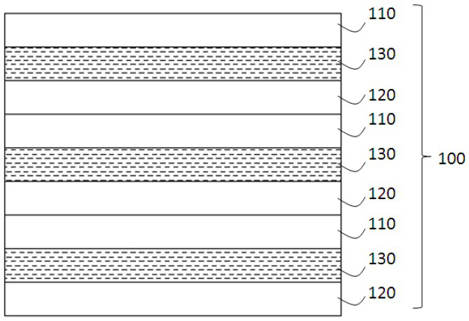
A composite insulating reflection layer (100), comprising: the composite insulation reflection layer (100) includes a plurality of dielectric pairs; at least one of the dielectric pairs includes a first material layer (110) with a first refractive index, and a second refractive index The second material layer (120) and the stress buffer layer (130) between them have a first refractive index greater than a second refractive index. The buffer layer (130) is used to reduce the production stress of the reflective film layer and improve the production yield of the chip process.

Description

technical field [0001] The invention relates to the field of semiconductor manufacturing, in particular to a composite insulating reflection layer. Background technique [0002] The existing distributed Bragg reflector (hereinafter referred to as: DBR) structure is made of periodic stacking of low refractive index and high refractive index materials, and the common low refractive index material is SiO 2 , high refractive index material is TiO 2 ; Usually the medium A / medium B that makes up the DBR can be any film or air, the old SiO 2 / TiO 2 The growth stress of the stacked film layer is relatively large, which is prone to cracking or peeling off of the film layer. [0003] see figure 1 , the existing DBR structure filling is a periodic stacking combination of two media with a large difference in refractive index, for example, the first material layer 110 and the second material layer 120 are stacked on each other, and the first material layer 110 and the second material...

Claims


Application Information

Patent Timeline
Patent Type & Authority Patents(China)
IPC IPC(8): H01L33/46H01L33/12H01L33/48
CPCH01L33/46H01L33/48H01L33/12H01L33/10H01L33/32H01L33/486H01L33/54H01L33/62
Inventor 张中英吴霁圃唐宏彬廖齐华邓有财张家豪邱树添
Owner XIAMEN SANAN OPTOELECTRONICS CO LTD
Learn More