Laser cutting machine with multi-angle adjustment function
A laser cutting machine, multi-angle technology, applied in the direction of laser welding equipment, welding equipment, metal processing equipment, etc., can solve the problems of ground impact, damage to the ground, and increase the speed of sliding down, so as to reduce the impact force and reduce the The influence of gravity and inertia, the effect of slowing down the falling speed
- Summary
- Abstract
- Description
- Claims
- Application Information
AI Technical Summary
Problems solved by technology
Method used
Image
Examples
Embodiment 1
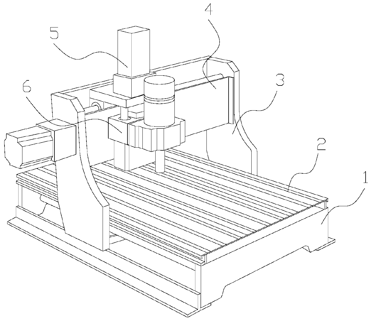
[0029] Example 1: Please refer to Figure 1-Figure 6 , the specific embodiments of the present invention are as follows:
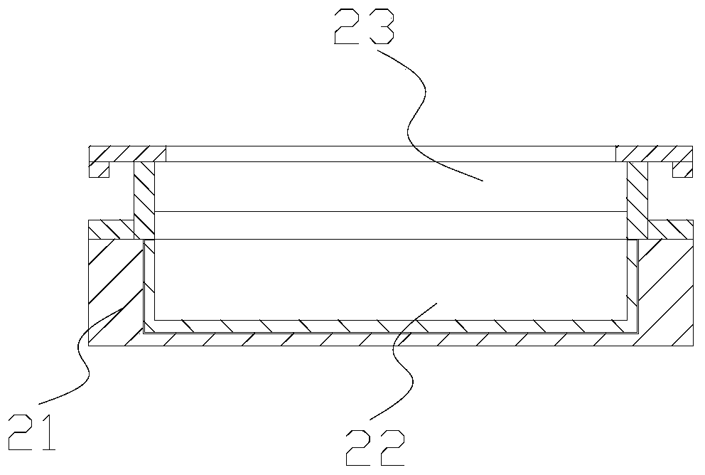
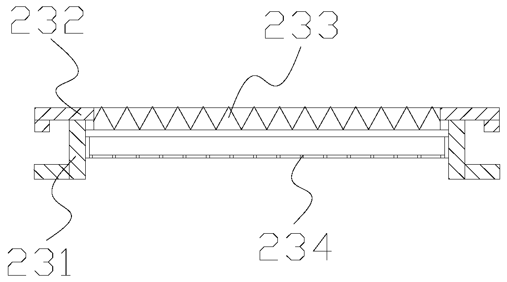
[0030] Its structure includes a base 1, a workbench 2, a mobile frame 3, a guide rail 4, a drive box 5, and a laser generator 6. The workbench 2 is horizontally installed on the inner side of the upper end of the base 1 and welded, and the mobile frame 3 is installed vertically. The two ends of the base 1 are flexibly connected, the guide rails 4 are horizontally fixed between the mobile frames 3 and welded together, the drive box 5 is sleeved on the outside of the guide rails 4 and connected by sliding, the laser generator 6 is installed At the lower end of the drive box 5 and fixed by bolts; the workbench 2 includes a fixed seat 21, a collection box 22, and a support structure 23. The collection box 22 is installed on the inside of the fixed seat 21 and is flexibly connected. Installed on the inner side of the base 1 and welded, the support structure 23...
Embodiment 2
[0036] Example 2: Please refer to Figure 5-Figure 10 , the specific embodiments of the present invention are as follows:
[0037] The opening structure 34c includes a frame c1, a bump c2, a guide structure c3, and a limit structure c4. The bump c2 is horizontally installed on the upper end of the frame c1 and welded together. The guide structure c3 is embedded and installed inside the frame c1 and adopts Hinge connection, the limiting structure c4 is embedded in the inner side of the frame c1 and adopts a flexible connection, and the limiting structure c4 is engaged with the side end of the guiding structure c3.
[0038] refer to Figure 7-Figure 8 The guide structure c3 includes a rotating block c31, a guide plate c32, a rotating shaft c33, and a curved spring c34. The guide plate c32 is horizontally installed on the right side of the rotating block c31 and welded together. The rotating shaft c33 runs through the inner side of the rotating block c31 and Hinge connection is...
PUM
 Abstract
Description
Claims
Application Information
 - R&D
- Intellectual Property
- Life Sciences
- Materials
- Tech Scout
- Unparalleled Data Quality
- Higher Quality Content
- 60% Fewer Hallucinations
Browse by: Latest US Patents, China's latest patents, Technical Efficacy Thesaurus, Application Domain, Technology Topic, Popular Technical Reports.
© 2025 PatSnap. All rights reserved.Legal|Privacy policy|Modern Slavery Act Transparency Statement|Sitemap|About US| Contact US: help@patsnap.com


