A multi-angle adjustable laser cutting machine

A laser cutting machine, multi-angle technology, used in laser welding equipment, metal processing equipment, welding equipment and other directions, can solve the problems of ground impact, damage to the ground, increase the speed of sliding down, reduce impact force, slow down Fall speed, effects of reducing the effects of gravity and inertia

Active Publication Date: 2022-06-28
山东罗迈刻智能装备有限公司
View PDF9 Cites 0 Cited by
  • Summary
  • Abstract
  • Description
  • Claims
  • Application Information

AI Technical Summary

Problems solved by technology

[0005] Aiming at the deficiencies in the prior art, the object of the present invention is to provide a multi-angle adjustable laser cutting machine to solve the problem that in the prior art, due to the large number of cutting angles, when an object is cut obliquely, the leftover material will follow its cutting. Slope downwards, and then with the inertia of the slide and the influence of gravity, the speed of the slide will gradually increase, which will generate greater kinetic energy, and the leftovers will fall to the ground, impacting the ground, and then destroying the ground. ground problem

Method used


Image

  • A multi-angle adjustable laser cutting machine
  • A multi-angle adjustable laser cutting machine
  • A multi-angle adjustable laser cutting machine

Examples


Embodiment 1

[0029] Example 1: Please refer to Figure 1-Figure 6 , the specific embodiment of the present invention is as follows:

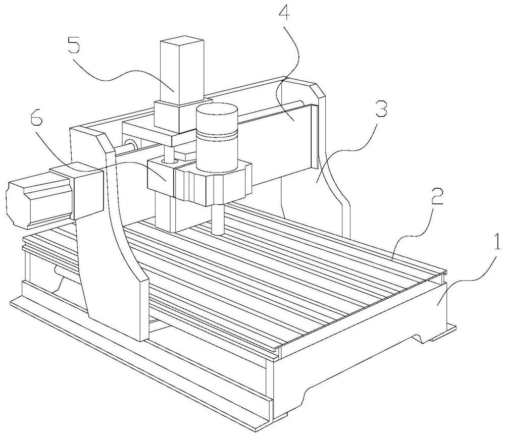
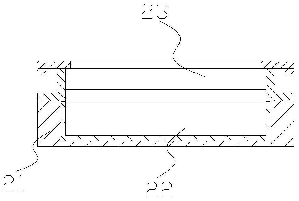
[0030] Its structure includes a base 1, a worktable 2, a moving frame 3, a guide rail 4, a drive box 5, and a laser generator 6. The worktable 2 is horizontally installed on the inner side of the upper end of the base 1 and welded to each other, and the moving frame 3 is installed vertically. On the inner side of both ends of the base 1 and adopt movable connection, the guide rail 4 is horizontally fixed between the moving frames 3 and welded, the drive box 5 is sleeved on the outside of the guide rail 4 and adopts a sliding connection, and the laser generator 6 is installed It is fixed at the lower end of the drive box 5 and fixed by bolts; the worktable 2 includes a fixed seat 21, a collection box 22, and a support structure 23. The collection box 22 is installed on the inner side of the fixed seat 21 and is movably connected, and the fixed seat 21 is embe...

Embodiment 2

[0036] Example 2: Please refer to Figure 5-Figure 10 , the specific embodiment of the present invention is as follows:

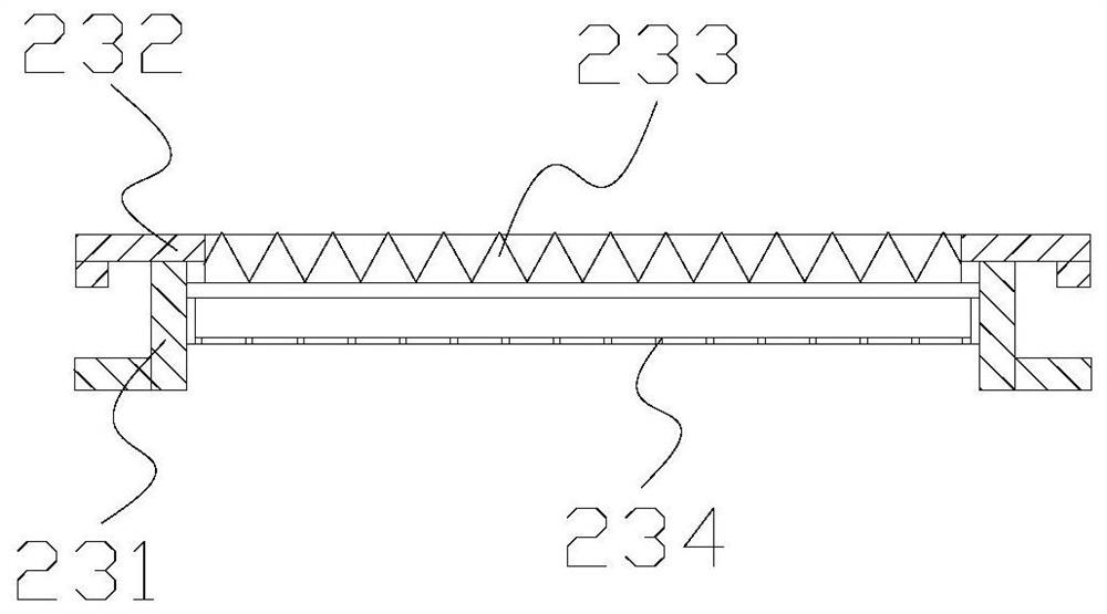
[0037] The opening structure 34c includes a frame c1, a protruding block c2, a guiding structure c3, and a limiting structure c4. The protruding block c2 is horizontally installed on the upper end of the frame c1 and welded to each other, and the guiding structure c3 is embedded in the inner side of the frame c1 and adopts Hinged connection, the limiting structure c4 is embedded in the inner side of the frame c1 and adopts an active connection, and the limiting structure c4 is engaged with the side end of the guiding structure c3.

[0038] see Figure 7-Figure 8 , the guide structure c3 includes a rotating block c31, a guide plate c32, a rotating shaft c33, and a curved spring c34, the guide plate c32 is horizontally installed on the right side of the rotating block c31 and welded to each other, and the rotating shaft c33 penetrates the inside of the rotat...


PUM


Abstract

The invention discloses a multi-angle adjustable laser cutting machine, which comprises a base, a workbench, a moving frame, a guide rail, a driving box, and a laser generator. On the inside of both ends, the guide rail is fixed horizontally between the moving frames, the drive box is set on the outside of the guide rail, the laser generator is installed on the lower end of the drive box, the workbench includes a fixed seat, a collection box, and a supporting structure, and the collection box is installed on the inside of the fixed seat. The fixing seat is embedded and installed inside the base. The present invention sets a support structure above the collection box, which reduces the impact of gravity and inertia while slowing down the falling speed, and increases the contact area to reduce the impact force. The leftovers are collected; an opening structure is set at the lower end of the feed port to guide the leftovers to adjust their falling angle, increase the falling contact area, and prevent the impact on the ground.

Description

technical field [0001] The invention belongs to the field of laser cutting, and particularly relates to a laser cutting machine with multi-angle adjustment. Background technique [0002] Laser cutting machines mainly use laser transmitters to emit high-power density laser beams to cut objects. With the increase of product types, the cutting and processing styles of objects also increase. The cutting of the style has derived a laser cutting machine with multi-angle adjustment, in which the working table of the laser cutting machine is hollow, and is supported by the combination of triangular blocks, and then the object is supported by point contact, but the existing technology has the following shortcomings : [0003] Due to the large number of cutting angles, when the object is cut obliquely, the scrap will slide down with the slope after cutting, and then with the inertia of the sliding and the influence of gravity, the speed of the downward sliding will gradually increase...

Claims


Application Information

Patent Timeline
Patent Type & Authority Patents(China)
IPC IPC(8): B23K26/38B23K26/16B23K26/70
CPCB23K26/38B23K26/16B23K26/702
Inventor 杨金银
Owner 山东罗迈刻智能装备有限公司
Why Eureka
Try Eureka