
A bolt support structure and construction method for railway embankment slope reinforcement

A bolt support and embankment technology, applied in infrastructure engineering, excavation, construction, etc., can solve problems such as potential safety hazards, long embankment slope extension, high reinforcement and maintenance costs, etc., to reduce ground resistance and reduce construction time , the effect of low noise

Active Publication Date: 2021-10-08
HARBIN INST OF TECH
View PDF0 Cites 0 Cited by
  • Summary
  • Abstract
  • Description
  • Claims
  • Application Information

AI Technical Summary

Problems solved by technology

However, when the traditional anchor rod is applied to the embankment slope, the drilling will cause vibration and the action of the grouting body during construction, which will have an adverse effect on the track, thus causing great safety hazards
In addition, the slope of the embankment has a long extension, and the cost of reinforcement and maintenance is high

Method used


Image

  • A bolt support structure and construction method for railway embankment slope reinforcement
  • A bolt support structure and construction method for railway embankment slope reinforcement
  • A bolt support structure and construction method for railway embankment slope reinforcement

Examples


specific Embodiment approach 1

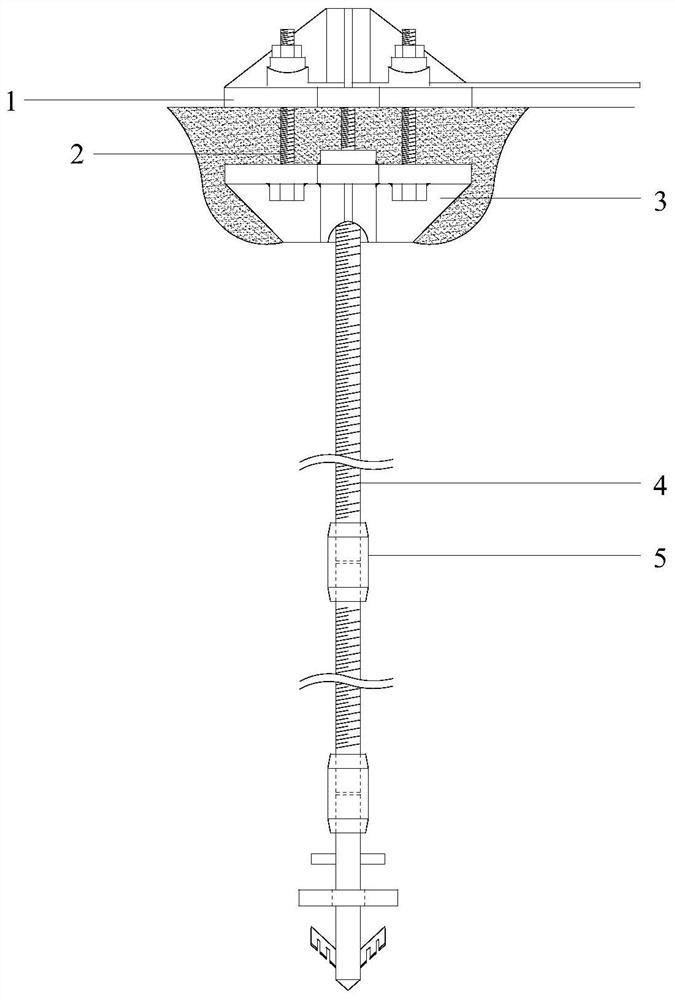
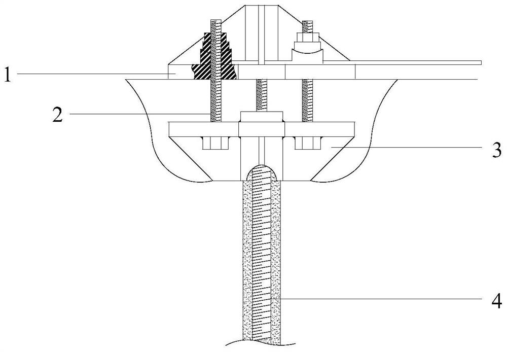
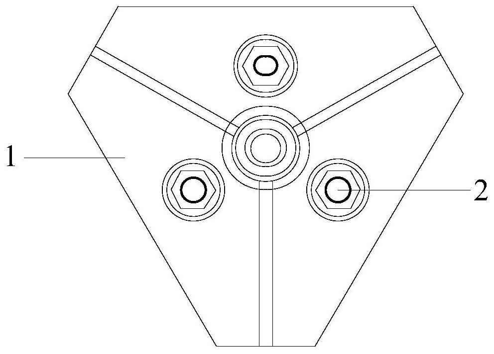
[0029] Specific implementation mode one: as Figure 1 to Figure 7 As shown, the present invention discloses a bolt support structure for railway embankment slope reinforcement, including a bolt body and an external pressure-bearing mechanism; the external pressure-bearing mechanism includes a pressure-bearing plate 1, a mounting member 3 and multiple One (three) support bolts 2; the pressure bearing plate 1 is arranged on the upper end of the installation member 3 and is arranged on the ground surface during use, and is detachably fixedly connected with the installation member 3 by a plurality of (three) support bolts 2, The bolt body includes a top-end digging mechanism, multi-section tensile steel bars 4 and a plurality of connectors 5; Tensile steel bars 4 and multiple connectors 5 are vertically stacked alternately and detachably fixedly connected, the upper end of the uppermost tensile steel bar 4 is detachably fixedly connected with the installation member 3, and the low...

specific Embodiment approach 2

[0030] Embodiment 2: This embodiment is a further description of Embodiment 1. The number of the multi-section tensile reinforcement bars 4 is the same as that of the plurality of connectors 5 .

specific Embodiment approach 3

[0031] Specific implementation mode three: as Figure 5 As shown, this embodiment is a further description of Embodiment 1. The protrusion 6 is a steel member with a triangular structure, and one corner is set downward.


PUM


Abstract

The invention discloses a bolt support structure and a construction method for reinforcing the slope of a railway embankment, belonging to the technical field of bolt support. The pressure bearing plate is fixed on the installation component and placed on the ground surface, the tensile steel bar and the connecting piece are fixed alternately up and down, the uppermost tensile steel bar is connected to the installation component, the lowermost connecting piece has protrusions on the lower end surface, and the circumferential surface has stirring wings, Rotary shaft connection of anti-rotor wing and excavation wing. Calculate the design values ​​and specifications of the bending moment, shear force, and axial force on the bolt body, connect the top excavation mechanism with the drilling machine, inject cement and stir it when drilling in, and stop working after it is completely drilled in and rotate it out in reverse , Connect the top excavation mechanism and the tensile steel bar, inject cement and stir at the same time, stop working after it is completely drilled; increase the tensile steel bar, drill repeatedly until reaching the predetermined depth, and fix the anchor rod. The invention reduces the number of pipelines, construction time and the number of anchor pieces, ensures the stability of the track, and improves the mixing efficiency of soil cement.

Description

technical field [0001] The invention relates to a bolt support structure and a construction method for reinforcing the side slope of a railway embankment, and belongs to the technical field of bolt support. Background technique [0002] Due to rain erosion, steep slope, improper construction and other reasons, embankment slope slide is one of the most common subgrade diseases. Because the bolt has the advantages of simple structure, good supporting effect, convenient construction and low cost, it is widely used in various engineering constructions. [0003] The existing anchor rod mainly provides anchoring force by pouring grout around the anchor rod and in the slope body, so that the anchor rod and the slope body form an integral body. However, when the traditional anchor rod is applied to the embankment slope, the drilling will cause vibration and the action of the grouting body during construction, which will have an adverse effect on the track, thus causing great safety...

Claims


Application Information

Patent Timeline
Patent Type & Authority Patents(China)
IPC IPC(8): E02D17/20E02D5/74
CPCE02D5/74E02D17/20
Inventor 凌贤长丛晟亦卢凡唐亮邢文强陈宏伟赵香萍
Owner HARBIN INST OF TECH
Learn More