control equipment for vehicles

A technology for controlling equipment and vehicles, applied in mechanical equipment, vehicle components, vehicle gearboxes, etc., can solve problems such as drivability degradation, and achieve the effects of simple transmission control, prevention of transmission stop, and reduction of torque transmission.

Active Publication Date: 2021-10-19
TOYOTA JIDOSHA KK
View PDF7 Cites 0 Cited by
  • Summary
  • Abstract
  • Description
  • Claims
  • Application Information

AI Technical Summary

Problems solved by technology

Stopping shifting can result in reduced drivability

Method used


Image

  • control equipment for vehicles
  • control equipment for vehicles
  • control equipment for vehicles

Examples


no. 1 example

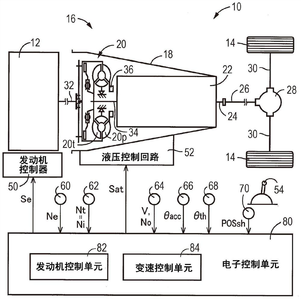
[0032] figure 1 is a diagram showing a schematic configuration of a vehicle 10 to which the present invention is applied, and is a diagram showing a main part of a control system for various controls in the vehicle 10 . Such as figure 1 As shown, the vehicle 10 includes an engine 12 as a power source, drive wheels 14 , and a power transmission device 16 provided in a power transmission path between the engine 12 and the drive wheels 14 . The power transmission device 16 includes a torque converter 20 and an automatic transmission 22 disposed inside a housing 18 that is a non-rotating component connected to the vehicle body. The power transmission device 16 includes a propeller shaft 26, a differential gear 28, a pair of drive shafts 30, and other parts. The prop shaft 26 is coupled to a transmission output shaft 24 which is the output rotating member of the automatic transmission 22 . A differential gear 28 is coupled to prop shaft 26 . A pair of drive shafts 30 are couple...

no. 2 example

[0076] In the first embodiment described above, in the shift control of the automatic transmission 22, the torque reduction control is executed. Torque reduction control may be performed only in shift control that may cause a large judder shock. In other words, the shift of the automatic transmission 22 that performs the torque reduction control is a predetermined shift that requires reducing the shock at the time of judder due to elimination of backlash in the automatic transmission 22 . For example, the predetermined shift is a shift control to change the automatic transmission 22 from the N position to the R position.

[0077] Figure 10 is a main part showing the control operation of the electronic control unit 80 (that is, in the shift control of the automatic transmission 22 for reducing the chattering while preventing the shift stop due to the delay of the engaging-side engaging device becoming engaged. The flow chart of the control operation of the impact). For exam...


PUM


Abstract

A control device for a vehicle is disclosed. Torque reduction control for temporarily reducing the torque capacity of the reaction engagement device is executed during shift transition. The reaction engagement device is kept in an engaged state from before the shift to after the shift so that a predetermined rotating element in the automatic transmission receives a reaction force due to a shift progress in which the engagement-side engagement device changes to the engaged state. Therefore, the transmission of torque due to judder during shift transition is reduced without delaying the change of the engagement-side engagement device into the engaged state. Therefore, in the shift control of the automatic transmission, the shock at the time of judder is reduced while preventing a shift stop due to a delay in changing the engaging-side engaging device to the engaged state.

Description

technical field [0001] The invention relates to a control device for a vehicle including an automatic transmission. Background technique [0002] There is known a control apparatus for a vehicle including an automatic transmission that changes gears by changing an operation state of a predetermined engagement device among a plurality of engagement devices. For example, this is a control device for a vehicle described in Japanese Unexamined Patent Application Publication No. 2004-347066 (JP 2004-347066 A). JP 2004-347066 A describes: when an automatic transmission is made to perform a shifting operation, when backlash (ie, looseness) remains in mechanical parts constituting a drive system of a vehicle, engaging the engaging side is reduced compared to normal The hydraulic pressure command value of the device engaged in the shifting operation of the automatic transmission is maintained for a predetermined duration from the start of the engagement so that the engagement-side e...

Claims


Application Information

Patent Timeline
Patent Type & Authority Patents(China)
IPC IPC(8): F16H61/02F16H61/04
CPCF16H61/0204F16H61/04F16D48/06F16D2500/10412F16D2500/1085F16D2500/30806F16D2500/30401F16D2500/70408F16D2500/7044F16H2061/0485F16H2061/0462F16H61/686F16H2200/2046F16H2200/201F16H3/663F16H2200/2023F16H2200/0069F16H61/4183F16D48/066F16H2061/1224F16H2061/2823F16H2061/0474
Inventor 日浦直树青野裕介松永仁
Owner TOYOTA JIDOSHA KK
Why Eureka
Try Eureka