Switching power supply controller, switching power supply system and switching power supply system power supply method

A switching power supply and controller technology, applied in the direction of control/regulation systems, instruments, electrical components, etc., can solve the problems of output voltage DCout load regulation and poor dynamic characteristics, achieve simple topology, low system cost, and improve load Effect of Regulation and Dynamics

Active Publication Date: 2021-08-06
SHANGHAI BRIGHT POWER SEMICONDUCTOR CO LTD
View PDF3 Cites 0 Cited by
  • Summary
  • Abstract
  • Description
  • Claims
  • Application Information

AI Technical Summary

Problems solved by technology

The output voltage DC OUT supplies power to the subsequent load, and in this switching power supply system, when working stably, the operating voltage (that is, the supply voltage) VCC of the control chip U0 is realized by the output voltage DC out through the diode D6 and the VCC sampling capacitor C3 , the VCC sampling capacitor C3 completes the sampling of the output voltage DC out and the power supply to the control chip U0, that is to say, the power supply mode of the control chip U0 is the power supply mode of the output voltage. This power supply mode of the control chip has good standby power consumption. However, since the VCC sampling capacitor C3 is required, and the sampling of the output voltage DC out is not direct sampling, the load regulation and dynamic characteristics of the output voltage DC out are poor.

Method used


Image

  • Switching power supply controller, switching power supply system and switching power supply system power supply method
  • Switching power supply controller, switching power supply system and switching power supply system power supply method
  • Switching power supply controller, switching power supply system and switching power supply system power supply method

Examples


Embodiment Construction

[0042] The technical solutions set forth in the present invention will be further described below with reference to the accompanying drawings and specific examples. The advantages and features of the present invention will be more clear depending on below. It is to be noted that the figures use a very simplified form and use non-precision ratios, only to convenient, clearly assisted in the purpose of explaining the embodiments of the present invention. Herein, the meaning of two components connections includes direct connections or indirectly through other components.

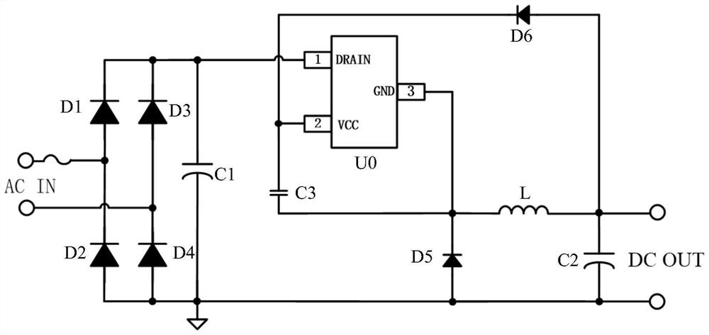
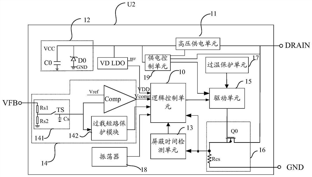
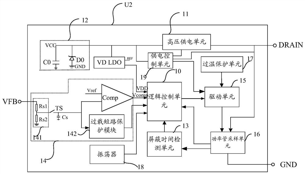
[0043] Please refer to Figures 2 to 4 In embodiment, an embodiment of the present invention provides a switching power source controller U2 for controlling an output voltage DC OUT of a switching power supply system. The switching power controller U2 includes: a logic control unit 10, a high voltage power supply unit 11, a built-in energy unit 12, a shielding time detecting unit 13, a voltage detecting unit 14, a d...


PUM


Abstract

The invention provides a switching power supply controller, a switching power supply system and a power supply method for the switching power supply system. unit and a logic control unit; wherein, the drive unit is used to drive the power switch tube to be turned on or off under the control of the logic control unit, so as to adjust the output voltage of the switching power supply system; the built-in storage The energy unit is used to supply power to the logic control unit. The invention can save the hardware consumption of the switching power supply system, reduce the power consumption of the system, and at the same time avoid the limitation on the size of the built-in energy storage capacitor.

Description

Technical field [0001] The present invention relates to the field of switching power supply, and in particular, to a switching power supply controller, a switching power supply system, and a switching power supply system power supply method. Background technique [0002] High-Side Buck AC-DC Switching Power Supply System is widely used in home appliances and electric meters. With the advancement of technology, the industry's performance requirements are increasing, and there is more efficient, lower. Standby power consumption, better EMI performance, better use flexibility, and lower cost. [0003] figure 1 For a commonly used HIGH SIDE BUCK AC-DC switching power supply system. After the grid AC side voltage is rectified by the rectified bridge consisting of diodes D1, D2, D3, D4, the control chip U0 is then output to an output voltage DC OUT, and the DC OUT is a fixed value. The output voltage DC OUT is supplied to the subsequent load, and in this switching power supply system,...

Claims


Application Information

Patent Timeline
Patent Type & Authority Patents(China)
IPC IPC(8): H02M7/217H02M3/156H02M1/08
CPCH02M3/156H02M1/08H02M7/219H02M1/36Y02B70/10
Inventor 江儒龙胡黎强孙顺根郜小茹陈一辉卢鹏飞朱臻张弘
Owner SHANGHAI BRIGHT POWER SEMICONDUCTOR CO LTD
Why Eureka
Try Eureka