Fire-fighting emergency lighting system and method based on centralized control type centralized power supply

An emergency lighting and fire emergency technology, applied in the direction of energy-saving control technology, electrical components, etc., can solve problems such as failure to play a key role, reliability, safety cannot be guaranteed, and product problems cannot be found in time

Inactive Publication Date: 2020-08-11
NANJING YANGTZE RIVER URBAN AGCHITECTURAL DESIGN
View PDF6 Cites 2 Cited by
  • Summary
  • Abstract
  • Description
  • Claims
  • Application Information

AI Technical Summary

Problems solved by technology

[0003] In related technologies, the design of emergency lighting usually adopts the method of adding batteries or centralized emergency power supply (EPS) to ordinary lamps, which not only cannot guarantee reliability and safety, but also requires inspection and maintenance because each emergency lighting lamp operates independently. Increased difficulty and inconvenient centralized management and control
In addition, in the emergency lighting system in the related art, there is no alarm signal when the lamps fail, and they can only rely on human maintenance and repair, and product problems cannot be found in time, causing a large number of emergency lighting lamps to be in a paralyzed state, which cannot be used in real emergency escape. play a key role in
At the same time, the power supply voltage of the lamp is 220V. In a fire state, electric leakage may occur, which will cause electric shock and casualties.

Method used


Image

  • Fire-fighting emergency lighting system and method based on centralized control type centralized power supply
  • Fire-fighting emergency lighting system and method based on centralized control type centralized power supply
  • Fire-fighting emergency lighting system and method based on centralized control type centralized power supply

Examples


Embodiment 1

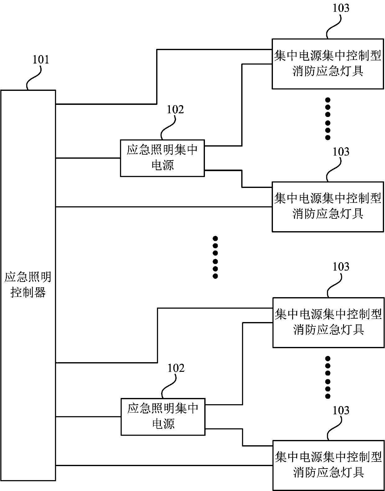
[0019] figure 1 It is a schematic structural diagram of a fire emergency lighting system based on a centralized control type centralized power supply provided by Embodiment 1 of the present invention. The embodiment of the present invention is applicable to the situation of setting fire emergency lighting in a building. Such as figure 1 As shown, the fire emergency lighting system based on centralized control type centralized power supply may specifically include: emergency lighting controller 101, at least two emergency lighting centralized power supplies 102 and at least two centralized power supply centralized control type fire emergency lighting fixtures 103, the following Its structure and function are described.

[0020] Among them, the emergency lighting controller 101 is set in the fire control room in the building, and communicates with the automatic fire alarm system, each emergency lighting centralized power supply 102 and each centralized power supply centralized...

Embodiment 2

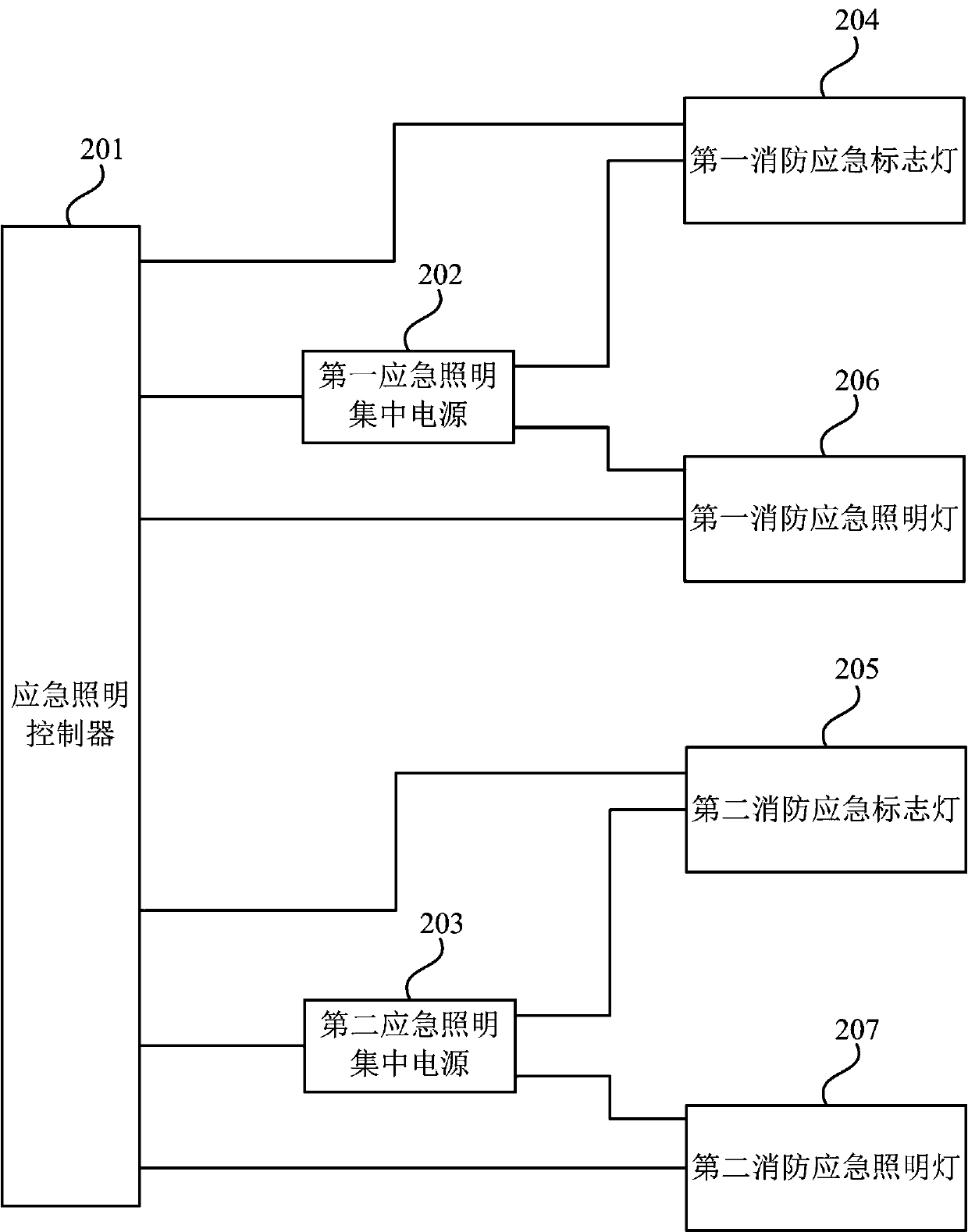
[0055] figure 2 It is a structural schematic diagram of a fire emergency lighting system based on a centralized control type centralized power supply provided by Embodiment 2 of the present invention. Such as figure 2 As shown, the fire emergency lighting system based on the centralized control type centralized power supply may specifically include: an emergency lighting controller 201, a first emergency lighting centralized power supply 202, a second emergency lighting centralized power supply 203, a first fire emergency sign light 204, a second The structures and functions of the second fire emergency light 205, the first fire emergency light 206 and the second fire emergency light 207 will be described below.

[0056] Specifically, the first centralized power supply for emergency lighting 202 , the second centralized power supply for emergency lighting 203 , the first fire emergency sign light 204 , the second fire emergency sign light 205 , the first fire emergency ligh...

Embodiment 3

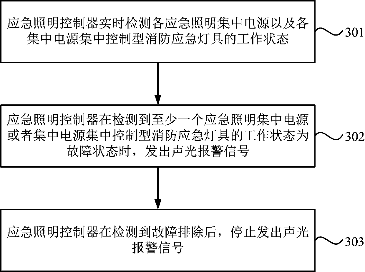
[0067] image 3 It is a flow chart of a fire emergency lighting method based on a centralized control type centralized power supply provided by Embodiment 3 of the present invention. The embodiment of the present invention is applicable to the situation of setting fire emergency lighting in a building. The method can be applied to the fire emergency lighting system based on the centralized control type centralized power supply provided by the above-mentioned embodiments of the present invention. Such as image 3 As shown, the method may specifically include the following steps:

[0068] Step 301, the emergency lighting controller detects in real time the working status of each emergency lighting centralized power supply and each centralized power supply centralized control type fire emergency lamp.

[0069] In this embodiment, the emergency lighting centralized power supply is a backup centralized emergency power supply device installed in the building. When a fire, accide...


PUM


Abstract

The embodiment of the invention discloses a fire-fighting emergency lighting system and method based on a centralized control type centralized power supply. The system comprises an emergency lightingcontroller, at least two emergency lighting centralized power supplies and at least two centralized power supply centralized control type fire-fighting emergency lamps, wherein the emergency lightingcontroller is arranged in a fire-fighting control room in a building and communicates with an automatic fire disaster alarm system, each emergency lighting centralized power supply and each centralized power supply centralized control type fire-fighting emergency lamp through buses. According to the technical scheme of the embodiment of the invention, emergency lighting centralized power supplies,centralized power supply centralized control type fire-fighting emergency lamps and an automatic fire disaster alarm system are arranged from a host to a line and at the tail end, a set of fire-fighting emergency lighting system based on a centralized control type centralized power supply is constructed, 24-hour uninterrupted inspection can be carried out, and through linkage with an automatic fire disaster alarm system in a building, on-site fire alarm information can be automatically acquired in time, and emergency starting is carried out.

Description

technical field [0001] The embodiments of the present invention relate to the field of signal devices, and in particular to a fire emergency lighting system and method based on a centralized control type centralized power supply. Background technique [0002] The national standard "Code for Fire Protection Design of Buildings" GB50016 stipulates where to set up fire emergency lighting in buildings. "Technical Standards for Fire Emergency Lighting and Evacuation Instruction System" GB51309 specifies how to design a fire emergency lighting system. [0003] In related technologies, the design of emergency lighting usually adopts the method of adding batteries or centralized emergency power supply (EPS) to ordinary lamps, which not only cannot guarantee reliability and safety, but also requires inspection and maintenance because each emergency lighting lamp operates independently. It increases the difficulty, and it is not convenient for centralized management and control. In ...

Claims


Application Information

Patent Timeline
IPC IPC(8): H05B45/30H05B45/10
CPCH05B45/10H05B45/30Y02B20/40
Inventor 范玉华
Owner NANJING YANGTZE RIVER URBAN AGCHITECTURAL DESIGN
Why Eureka
Try Eureka