Method for temporary mooring point and cable rope fixing point

A cable wind rope and fixed point technology, which is applied in the field of large-scale equipment assembly, can solve the problems of high construction cost and period, and no suitable fixed point for safety cables, and achieve high utilization efficiency, low construction period and use cost, and rapid deployment Effect

Inactive Publication Date: 2016-10-12
SHANGHAI ZHENHUA HEAVY IND
View PDF4 Cites 0 Cited by
  • Summary
  • Abstract
  • Description
  • Claims
  • Application Information

AI Technical Summary

Problems solved by technology

[0005] The technical problem to be solved by the present invention is to provide a temporary mooring point and a method for fixing the wind rope in order to overcome the defects in the prior art that there is no suitable fixing point for the safety cable, and the construction cost and cycle are very large.

Method used


Image

  • Method for temporary mooring point and cable rope fixing point
  • Method for temporary mooring point and cable rope fixing point
  • Method for temporary mooring point and cable rope fixing point

Examples


Embodiment 1

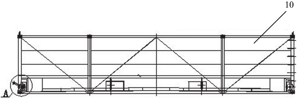
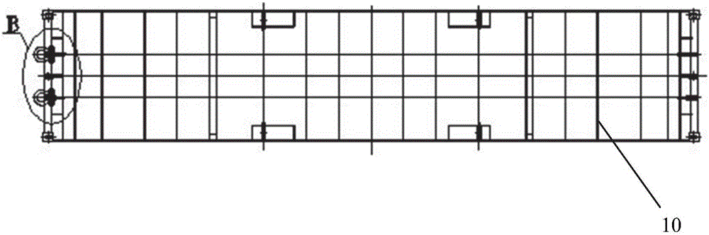
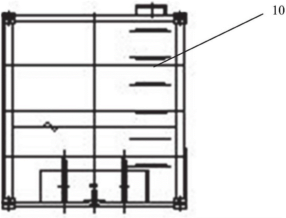
[0033] figure 1 Front view of a water tank for a 40 foot ground anchor in the method of the present invention for temporary mooring points and cable wind rope fixing points. figure 2 Top view of the water tank for the 40 foot ground anchor in the method of the present invention for temporary mooring points and wind rope anchorage points. image 3 Side view of the water tank for the 40 foot ground anchor in the method of the present invention for temporary mooring points and windline anchorage points. Figure 4 for figure 1 Enlarged view of part A in Fig. Figure 5 for figure 2 Enlarged view of part B in . Figure 6 It is a schematic diagram of the water tank combination of two 40-foot ground anchors in the method of temporary mooring point and cable wind rope fixing point of the present invention.

[0034] Such as Figure 1 to Figure 6 As shown, the present invention discloses a method for a temporary mooring point and a fixed point of a cable wind rope, which includes...

Embodiment 2

[0043] Figure 7 Front view of a 20 foot trial weighted water tank for the temporary mooring point and wind rope anchorage point method of the present invention. Figure 8 Top view of a 20 foot trial weighted water tank for the method of the present invention for temporary mooring points and wind rope anchorage points. Figure 9 Side view of a 20 foot trial weight tank for the temporary mooring point and windline anchorage point method of the present invention. Figure 10 It is the combination schematic diagram of the water tank of the ground anchor of 40 feet and the water tank of 20 feet of test weight in the method for temporary mooring point and cable wind rope fixed point of the present invention.

[0044] Such as Figure 7 to Figure 10 shown, combined with Figure 1 to Figure 5 , the invention discloses a method for a temporary mooring point and a fixed point of a cable wind rope, which comprises the following steps:

[0045] Step 1. The water tanks using multiple gr...


PUM


Abstract

The invention provides a method for temporary mooring points and cable rope fixing points. The method includes the following steps that firstly, water tanks with multiple ground anchors are arranged side by side, and wood plates are laid between the water tanks and the ground; secondly, the water tanks are connected into a whole through steel wire ropes; and thirdly, when other devices are provided with cables, mooring ropes and the steel wire ropes on the water tanks are connected into a whole to form the mooring points. By means of the method for the temporary mooring points and the cable rope fixing points, the temporary mooring points and the cable rope fixing points can be rapidly arranged during engineering construction and put into use in time and are short in construction period, low in use cost and high in utilization efficiency.

Description

technical field [0001] The invention relates to the field of large-scale equipment assembly, in particular to a method for a temporary mooring point and a fixed point of a cable wind rope. Background technique [0002] In the field of large-scale equipment assembly, when large-scale floating cranes are operating on various wharves, the rated pulling force of the bollards on the wharf may be lower than the pulling force of the floating crane cables, and there may be unsafe factors in floating crane operations. [0003] When there are some unstable stages during the installation of some large equipment, it is necessary to design a safety cable to fix it to increase safety, but there is no suitable fixing point for the safety cable. [0004] If a large cable pile or fixed point is built according to the tension requirement, the period and cost are very large, and the utilization rate is very low. For this reason, this application has developed a set of temporary mooring points ...

Claims


Application Information

Patent Timeline
IPC IPC(8): E02B3/20E02D5/80
CPCE02B3/20E02D5/80
Inventor 罗庆周井华周力伟李小红俞丽居健
Owner SHANGHAI ZHENHUA HEAVY IND
Why Eureka
Try Eureka