High-frequency cavity of current control ultra-wideband cyclotron

A cyclotron and current control technology, applied in the direction of magnetic resonance accelerators, electrical components, accelerators, etc., can solve the problems of increased processing difficulty and cost of tuning rods, unfavorable installation and debugging, and increase the difficulty of magnet system design, etc., to reduce installation Difficulty in debugging, reduction in vertical footprint, reduction in processing difficulty and cost

Inactive Publication Date: 2020-08-11
HARBIN INST OF TECH
View PDF13 Cites 0 Cited by
  • Summary
  • Abstract
  • Description
  • Claims
  • Application Information

AI Technical Summary

Problems solved by technology

There are two main problems caused by this: first, an excessively high tuning rod increases processing difficulty and cost, which is not conducive to installation and debugging; second, an excessively high frequency tuning structure will interfere with other subsystems of the accelerator, such as the structure of the magnet system. Interference occurs, increasing the design difficulty of the magnet system
Therefore, for a high-frequency cavity with a relative bandwidth exceeding 30%, the traditional frequency tuning structure is difficult to meet the design requirements

Method used


Image

  • High-frequency cavity of current control ultra-wideband cyclotron
  • High-frequency cavity of current control ultra-wideband cyclotron
  • High-frequency cavity of current control ultra-wideband cyclotron

Examples


Embodiment Construction

[0026] It should be noted that, in the case of no conflict, the embodiments of the present invention and the features in the embodiments can be combined with each other.

[0027] The present invention will be described in detail below with reference to the accompanying drawings and examples.

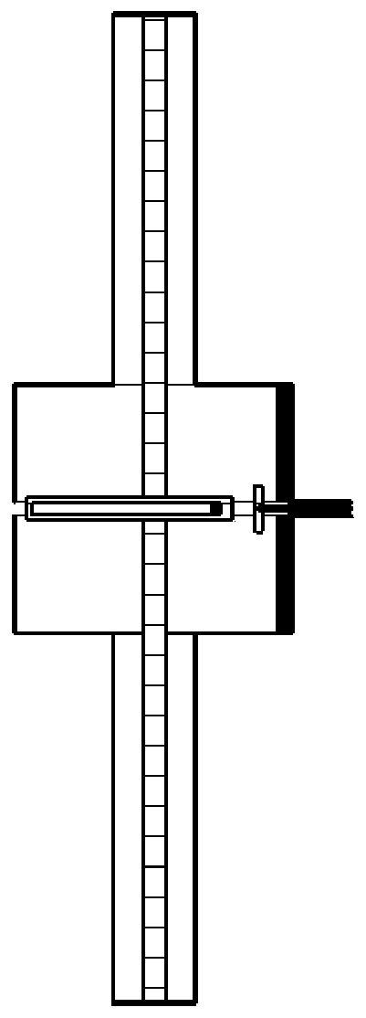
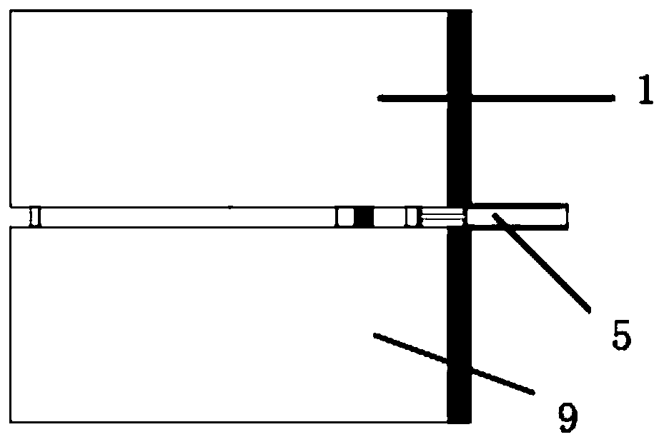
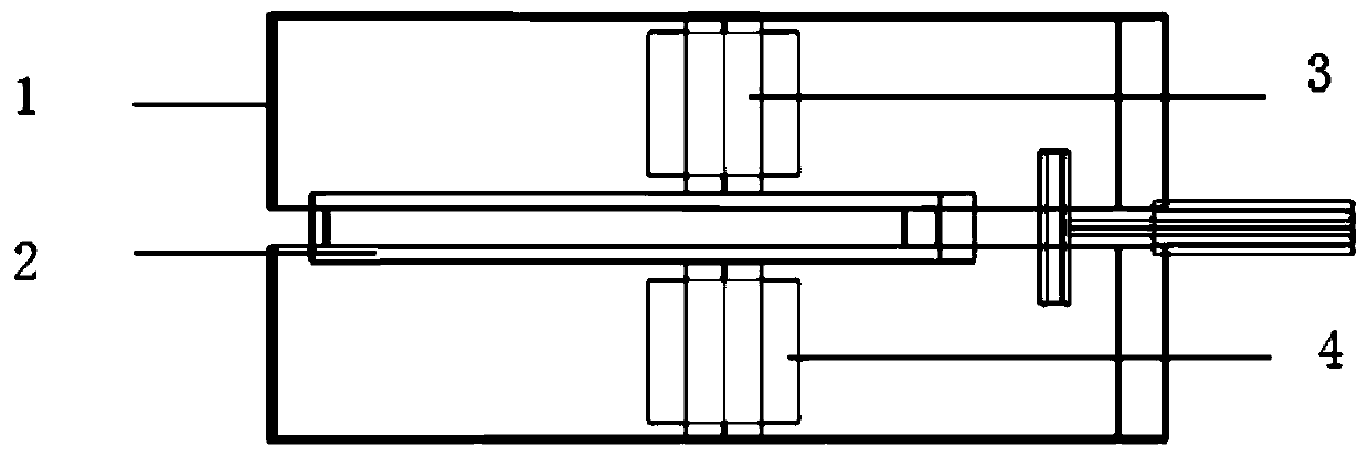
[0028] Such as Figure 2-Figure 5 As shown, a high-frequency cavity of a current-controlled ultra-broadband cyclotron includes an upper casing 1, a lower casing 9, an accelerating electrode Dee box 2, a ferrite 4, a tuning rod 3 and a feed structure 5, and the upper casing 1 and the lower casing 9 have the same structure and are symmetrically arranged. There is a gap between the upper casing 1 and the lower casing 9, and one end of the upper casing 1 and the lower casing 9 is connected, and the accelerating electrode Dee box 2 is arranged on At the gap between the upper shell 1 and the lower shell 9, there are gaps between the left and right sides of the accelerating electrode Dee box 2...


PUM


Abstract

The invention provides a high-frequency cavity of a current control ultra-wideband cyclotron. The high-frequency cavity comprises an upper shell, a lower shell, an accelerating electrode Dee box, a ferrite, a tuning rod and a feed structure. The upper shell and the lower shell have the same structure, and are symmetrically arranged. The upper shell is connected with one end of the lower shell. Theaccelerating electrode Dee box is arranged at a gap between the upper shell and the lower shell. Gaps are formed between two sides of the accelerating electrode Dee box and the shell. The upper sideand the lower side of the accelerating electrode Dee box are respectively and vertically connected with a tuning rod. One tuning rod is arranged in the upper shell, the other tuning rod is arranged inthe lower shell, the tail end of each tuning rod is connected with the corresponding shell, the outer surface of each tuning rod is wrapped with ferrite, the ferrite is externally connected with a direct current source, and the feed structure is inserted into the high-frequency cavity from the connecting end of the upper shell and the lower shell. According to the invention, a cylindrical frequency tuning structure with a huge volume is replaced by ferrite loading, and ultra-wideband tuning is realized by changing the current of a ferrite material.

Description

technical field [0001] The invention belongs to the field of particle accelerators, in particular to a high-frequency cavity of a current-controlled ultra-broadband cyclotron. Background technique [0002] The cyclotron can realize the acceleration and deflection of ions, and the ion acceleration is realized by the high-frequency electromagnetic field excited inside the high-frequency cavity. In order to accelerate a variety of different ions to a specified energy, the frequency range of the high-frequency electromagnetic field of the cyclotron should be ultra-wideband, and its relative bandwidth can reach 30% or even 70% of the center frequency. In order to achieve ultra-broadband tuning of the working frequency, traditional cyclotrons usually use a frequency tuning structure in the high frequency cavity of the accelerator. The frequency tuning structure usually includes a tuning rod, a cylinder and a short circuit. Adjusting the position of the short circuit can change th...

Claims


Application Information

Patent Timeline
Patent Type & Authority Applications(China)
IPC IPC(8): H05H13/00H05H7/18
CPCH05H13/005H05H7/18
Inventor 陈晚郝焕锋蒋洪平刘剑利张健张韬陈启明韩正男姚庆欢李忠宇李振宇窦彦昕
Owner HARBIN INST OF TECH
Why Eureka
Try Eureka