
Stamping equipment for bus duct machining and fixing method of stamping equipment for bus duct machining

A technology for stamping equipment and fixing methods, which is applied in the direction of metal processing equipment, metal processing, forming tools, etc., can solve the problems of large safety hazards and poor continuity of stamping processing, and achieve high safety, stable stamping process, and good continuity Effect

Inactive Publication Date: 2020-08-14
镇江西杰电气有限公司
View PDF15 Cites 5 Cited by
  • Summary
  • Abstract
  • Description
  • Claims
  • Application Information

AI Technical Summary

Problems solved by technology

[0007] The purpose of the present invention is to provide a punching equipment for bus duct processing and its fixing method, so as to solve the problems of poor continuity of punching processing and great potential safety hazards in the above-mentioned background technology

Method used


Image

  • Stamping equipment for bus duct machining and fixing method of stamping equipment for bus duct machining
  • Stamping equipment for bus duct machining and fixing method of stamping equipment for bus duct machining
  • Stamping equipment for bus duct machining and fixing method of stamping equipment for bus duct machining

Examples


Embodiment Construction

[0029] The following will clearly and completely describe the technical solutions in the embodiments of the present invention with reference to the accompanying drawings in the embodiments of the present invention. Obviously, the described embodiments are only some, not all, embodiments of the present invention. Based on the embodiments of the present invention, all other embodiments obtained by persons of ordinary skill in the art without making creative efforts belong to the protection scope of the present invention.

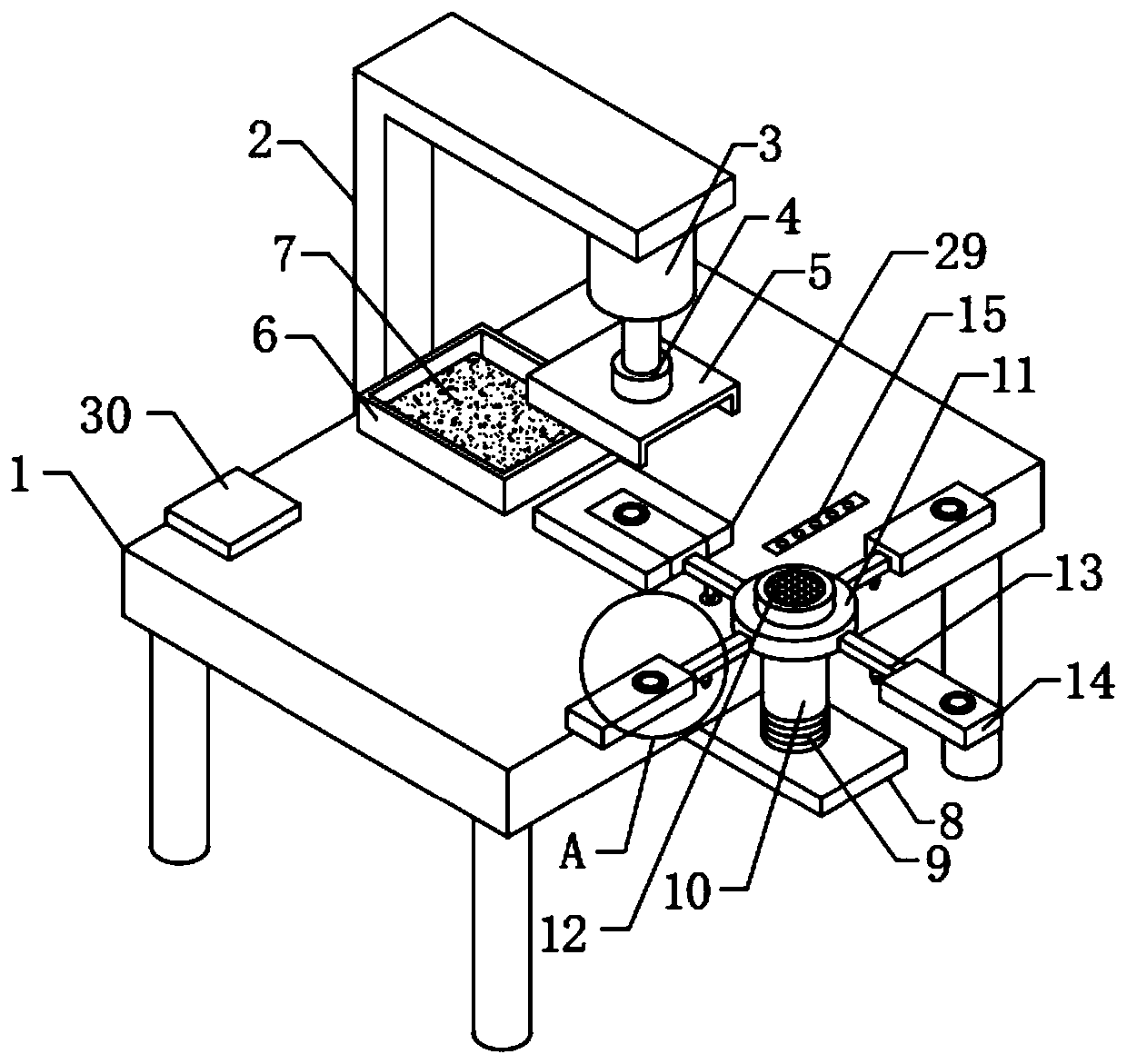
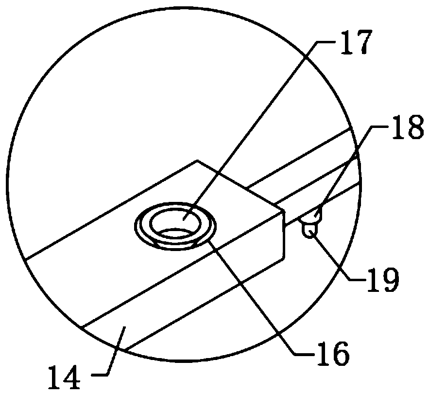
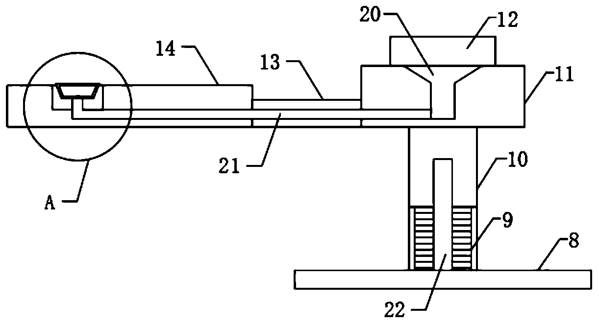
[0030] see Figure 1-6 , the present invention provides a technical scheme of stamping equipment for bus duct processing:

[0031] according to Figure 1-Figure 6 As shown, it includes a stamping table 1, the middle part of the side wall of the stamping table 1 is fixedly connected with an L-shaped mounting frame 2, and the side wall of the top of the L-shaped mounting frame 2 is fixedly installed with a cylinder 3, and the output end of the cylinder 3 is con...


PUM


Abstract

The invention discloses stamping equipment for bus duct machining and fixing method of the stamping equipment for the bus duct machining. The stamping equipment comprises a stamping table, an L-shapedinstalling frame is fixedly connected to the middle of one side wall of the stamping table, an air cylinder is fixedly installed on one side wall of the top of the L-shaped installing frame, a connecting block is in transmission connection with the output end of the air cylinder, an upper mold is fixedly connected to the bottom end of the connecting block, a first lower mold is connected to the middle of the top end of the stamping table in a clamped mode, a storage box is connected to one side of the top end of the stamping table in a sliding mode, a sponge block is fixedly connected to themiddle of the inner wall of the bottom end of the storage box, and an installing plate is fixedly connected to one side of the bottom end of the stamping table. According to the stamping equipment forthe bus duct machining and the fixing method of the stamping equipment for the bus duct machining, a rotating plate is arranged, by means of cooperation of multiple connecting rods and multiple second lower molds, multiple stamping materials can be placed in the area outside the air cylinder, hands are prevented from being crushed by the air cylinder, safety is higher, and the multiple stamping materials can be rapidly and stably fixed by means of cooperation of multiple suction cups and multiple air guide pipes.

Description

technical field [0001] The invention relates to a stamping equipment, in particular to a stamping equipment for bus duct processing and a fixing method thereof. Background technique [0002] Busway is a closed metal device composed of copper and aluminum busbar columns, which is used to distribute large power to various components of the decentralized system. It has been increasingly replaced in indoor low-voltage power transmission main line projects. Wire and cable, with the emergence of modern engineering facilities and equipment, the power consumption of all walks of life is increasing rapidly, especially the emergence of many high-rise buildings and large workshops, traditional cables used as transmission wires can no longer be used in large current transmission systems To meet the requirements, the parallel use of multi-channel cables has brought a lot of inconvenience to the site installation and construction connection, and the plug-in busway has emerged as a new typ...

Claims


Application Information

Patent Timeline
Patent Type & Authority Applications(China)
IPC IPC(8): B21D22/08B21D43/00B21C51/00B21D37/18
CPCB21D22/08B21D43/003B21C51/00B21D37/18
Inventor 郭春松王俊
Owner 镇江西杰电气有限公司
Learn More