Cutting roller group of steel cut wire shot equipment

A technology for cutting steel wire shot and cutting roller, which is applied in the processing field of metal abrasives, can solve the problem of high tool wear speed, etc., and achieve the effect of reducing the failure rate, reducing the time interval and increasing the service life

Inactive Publication Date: 2020-08-14
王认认
View PDF0 Cites 2 Cited by
  • Summary
  • Abstract
  • Description
  • Claims
  • Application Information

AI Technical Summary

Problems solved by technology

Existing steel wire cutting machine is that the cutting tool cuts the steel wires row by row, and the output power of the motor needs to exceed the minimum power that a row of steel wires are cut off; the cutting tool is cut by intermittent motion, and when the cutter cuts the steel wire, One edge of the tool has always acted on the steel wire, and the friction generates a lot of heat, causing the tool to wear quickly

Method used


Image

  • Cutting roller group of steel cut wire shot equipment
  • Cutting roller group of steel cut wire shot equipment
  • Cutting roller group of steel cut wire shot equipment

Examples


Embodiment Construction

[0025] It should be understood that the specific embodiments described here are only used to explain the present invention, not to limit the present invention.

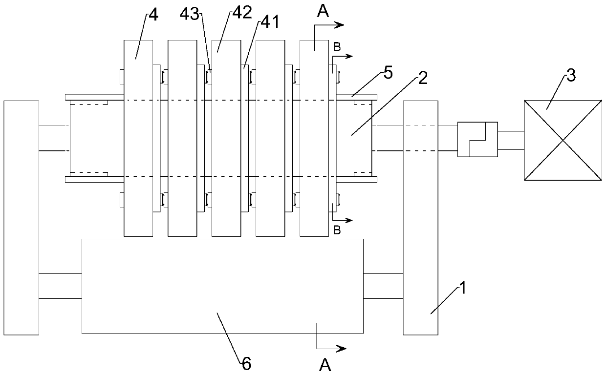
[0026] Such as figure 1 , 2 , a steel wire shot cutting equipment cutting roller group, including a support frame 1, a rotating shaft 2, a motor 3, a cutting device 4, a threaded sleeve 5, a pressure roller 6 and an orientation column 7, the upper and lower parts of the support frame 1 Both ends are provided with two through holes; the rotating shaft 2 is arranged on the upper part of the supporting frame 1, and one end of the rotating shaft 2 is arranged in the through hole of the supporting frame 1, and the other end of the rotating shaft 2 passes through the supporting frame The through hole of 1 is connected with the motor 3, the two ends of the rotating shaft 2 are provided with threads, and the said rotating shaft 2 is provided with grooves.

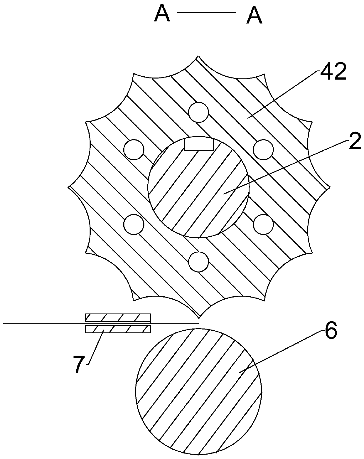
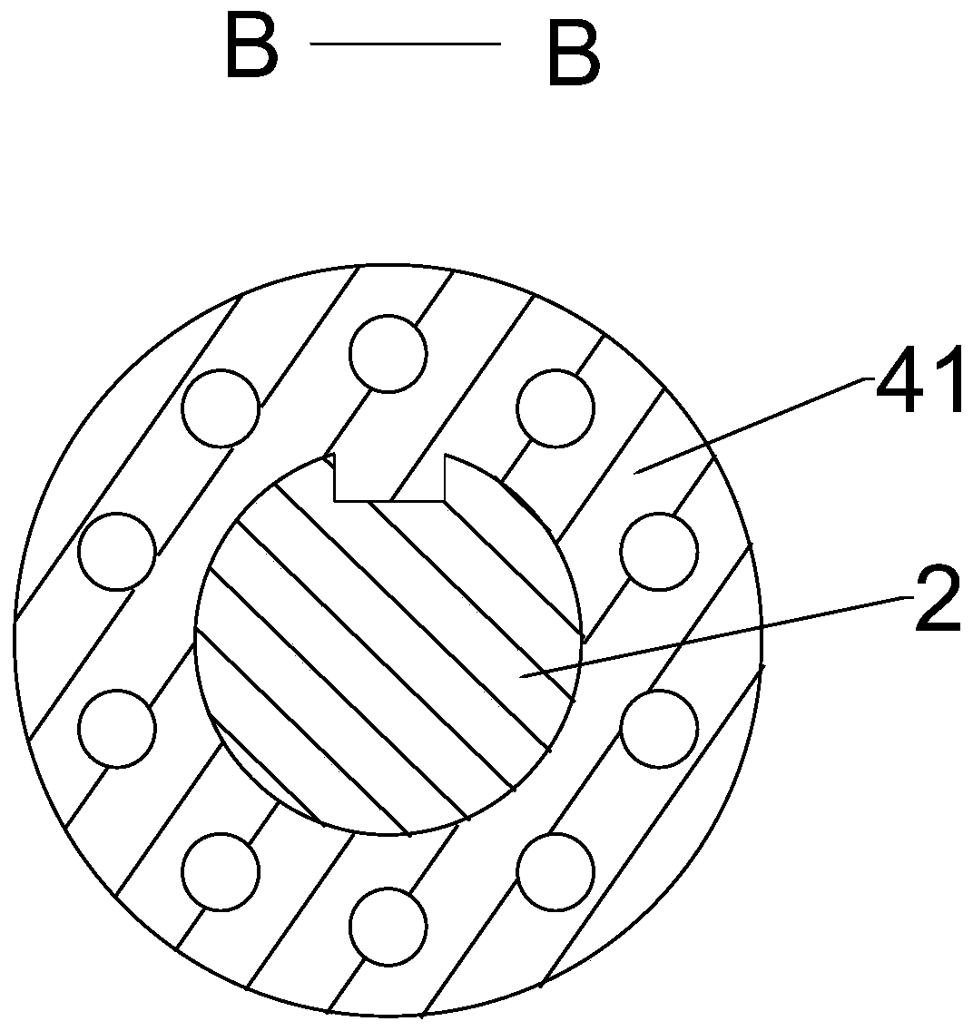
[0027] Such as figure 1 , 2 , 3, the number of the cutting device...


PUM


Abstract

The invention relates to the field of metal abrasive processing, in particular to a cutting roller group of steel cut wire shot equipment. The cutting roller group includes a supporting frame, a rotating shaft, a motor, a plurality of cutting device, threaded sleeves, a pressure-bearing roller and an orientation column; the rotating shaft is arranged on the upper part of the supporting frame, oneend of the rotating shaft penetrates through a through hole of the supporting frame and is connected to the motor, the pressure-bearing roller is arranged on the lower part of the supporting frame, the cutting devices are arranged in a linear shape, each cutting device rotates on the self-axis at a certain angle relative to the previous cutting device to be installed on the rotating shaft, the threaded sleeves are arranged on threads at the two ends of the rotating shaft, and the orientation column is arranged on the front of the supporting frame. The cutting devices are arranged on the same rotating shaft, the centralized one-time cutting of a steel wire is turned into single scattered cutting, the time for cutting the steel wire is divided, the use efficiency of the motor is improved, and meanwhile, the impact of a cutting tool cutting the steel wire is reduced and uniform, so that the failure rate of the cutting devices is reduced.

Description

technical field [0001] The invention relates to the processing field of metal abrasives, in particular to a cutting roller group of steel wire shot cutting equipment. Background technique [0002] Metal abrasives are widely used in industrial production and processing. They are commonly used in shot blasting equipment, shot peening equipment and sandblasting equipment to achieve the purpose of removing sand, rust, oxidation, and strengthening structures. The most commonly used metal abrasives are steel wire cut shot , Steel wire cut shot is made by cutting steel wire by machine. Existing steel wire cutting machine is that the cutting tool cuts the steel wires row by row, and the output power of the motor needs to exceed the minimum power that a row of steel wires are cut off; the cutting tool is cut by intermittent motion, and when the cutter cuts the steel wire, It has always been that one edge of the tool acts on the steel wire, and the friction generates a lot of heat, w...

Claims


Application Information

Patent Timeline
Patent Type & Authority Applications(China)
IPC IPC(8): B21F11/00B21F23/00
CPCB21F11/00B21F23/00
Inventor 王认认
Owner 王认认
Why Eureka
Try Eureka