Peak power management and active decoupling arrangement for span-powered remote terminal access platforms

a remote access platform and power management circuit technology, applied in the direction of telephonic communication, electric variable regulation, energy consumption reduction, etc., can solve the problems of arbitrary increases in span voltage to meet powering requirements of remote equipment, limited by telecom industry standards, safety requirements, etc., to reduce the maximum power, reduce the maximum peak current, and reduce the maximum power

Inactive Publication Date: 2005-09-22
ADTRAN
View PDF4 Cites 0 Cited by
  • Summary
  • Abstract
  • Description
  • Claims
  • Application Information

AI Technical Summary

Benefits of technology

[0014] In a complementary manner, when the load on the ring generator exceeds the output power of the voltage converter, the isolating voltage begins to decrease, releasing energy from the reservoir capacitor into the ring generator. The isolating voltage and the reservoir capacitor are chosen to provide enough energy to enable the ring generator to sustain a predetermined load for a minimum amount of time. If the isolating voltage becomes too small, an isolation voltage monitoring circuit outputs a signal to the remote terminal's controller to cause the ring cadence to be reduced, which effectively reduces the load on ring generator.
[0024] The amplifier's output controls a buffering device, such as a bipolar transistor, having its controlled current flow (collector-emitter) path coupled between ground and the COMP port of the PWM controller. When the input voltage is sufficiently high, the output of the amplifier is forced to it's highest value, which reverse-biases the transistor and the power-limited converter operates as described above. When the input voltage drops to a low value (indicating too much power is being drawn by the system), the amplifier's output voltage is reduced, so that the buffering device controlled thereby conducts, to pull the input port of the PWM controller to a lower voltage. This reduces the maximum current sense voltage which, in turn, reduces the maximum peak current through the primary winding of the transformer and decreases the maximum power the converter can extract from the line.

Problems solved by technology

Unfortunately, the power delivered by the ring generator (and thus delivered to it) can be expected to fluctuate substantially over time, because of the time-varying nature of the ringing waveform and the statistically changing load requirements.
VCO is limited by telecom industry standards, safety requirements, and voltage breakdown limitations of some twisted pair telephone cable.
Therefore, arbitrary increases in span voltage to meet powering requirements of the remote equipment are not feasible.
A second problem is that noise associated with the generation of the ringing voltage can mix with the DSL signal, and cause significant performance problems for the DSL signal.
Some DSL systems are very sensitive to ringing voltage ripple because the 20 Hz ring frequency is high enough to interfere with the signal, yet too low for the analog-or-digital filters of the signal path to attenuate.
Passive power filtering between the remote terminal's input and the ringing generator requires a physically large circuit and may not be practical, because of the low frequency and the amount of attenuation required.
While the linear nature of this current limiting circuit results in a power dissipation that is acceptable for single subscriber line applications, it is not feasible for use with a remote access platform serving considerably more than one line (e.g., twenty-four lines in one present day remote terminal device) and having a potentially much higher ringing power, where a linear (dissipative) circuit to limit peak power is not acceptable.
This power demand problem also occurs in hybrid schemes that are capable of extracting both local power and span power for operating the remote terminal equipment.
Now although the power management scheme described in the '382 is a relatively cost-effective architecture, due to the low power and simultaneous dual power input nature of the remote terminal, it is not particularly suited for higher power and single input (wireline only) applications.

Method used


Image

  • Peak power management and active decoupling arrangement for span-powered remote terminal access platforms
  • Peak power management and active decoupling arrangement for span-powered remote terminal access platforms

Examples


Embodiment Construction

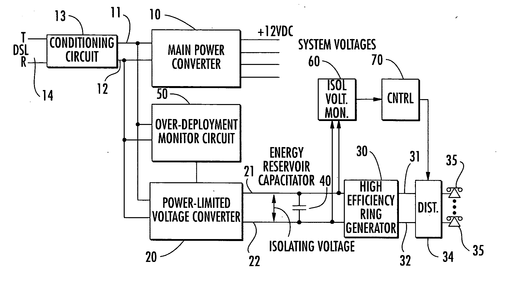
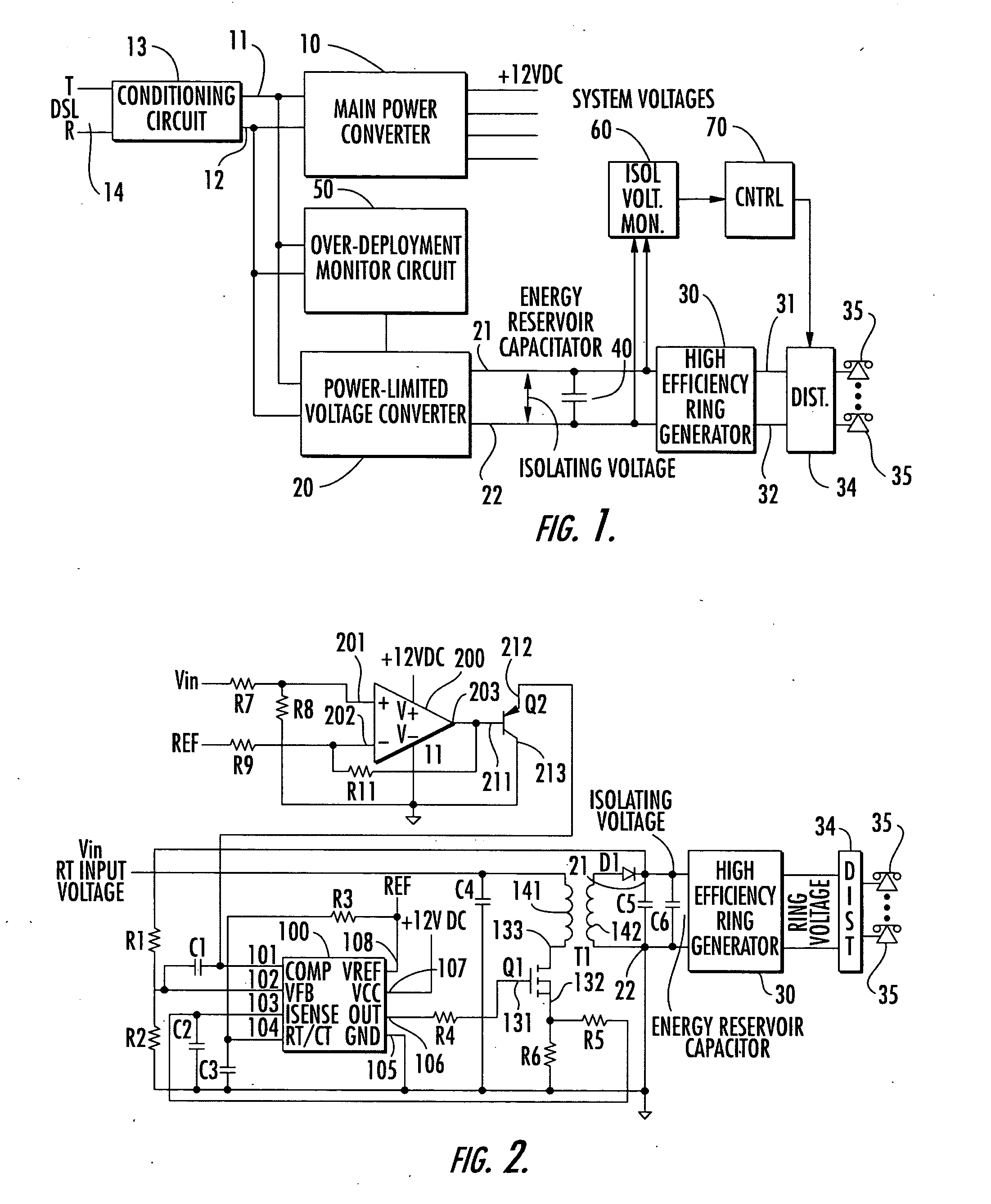
[0027] Before detailing the peak power management and active decoupling arrangement of the present invention, it should be observed that the invention resides primarily in a prescribed arrangement of conventional wireline telecommunication and power converter hardware circuits and components therefor. Consequently, the configuration of such circuits and components and the manner in which they may be interfaced with a telecommunication wireline pair have, for the most part, been illustrated in the drawings by readily understandable block diagrams and attendant schematics, which show only those specific details that are pertinent to the present invention, so as not to obscure the disclosure with details which will be readily apparent to those-skilled in the art having the benefit of the description herein. Thus, the diagrammatic illustrations of the Figures are primarily intended to show the major elements of the invention in convenient functional groupings, whereby the present invent...


PUM


Abstract

A power management circuit for a remote access platform extracts power from a wireline for powering a ring generator that generates a ringing voltage signal that is distributed to a plurality of subscriber circuits. A power-limited voltage converter steps up the wireline voltage to a higher ‘isolating’ voltage, charging a capacitor coupled to the ring generator. A monitor circuit reduces the power that the power-limited voltage converter can draw, if the wireline voltage drops too low. This prevents the wireline voltage from collapsing should the remote terminal be deployed at a distance from wireline voltage source (the central office) greater than its specified capability.

Description

FIELD OF THE INVENTION [0001] The present invention relates in general to a power management circuit for a span-powered remote access platform generating a ringing voltage distributed to a plurality of subscriber circuits. A power-limited voltage converter steps up the span-derived voltage to a higher ‘isolating’ voltage to charge an energy reservoir capacitor coupled across voltage inputs to a ring generator. A monitor circuit reduces the power that the power-limited voltage converter can draw, if the (span) voltage drops too low. This prevents the input voltage from collapsing should the remote terminal be deployed at a distance from the central office greater than its specified capability. BACKGROUND OF THE INVENTION [0002] Digital subscriber line (DSL) technologies, such as HDSL and HDSL2, are currently used by telecommunication service providers to deliver services such as ADSL, SHDSL, ISDN and POTS to terminal access platforms at remote (customer premises) installations. In ad...

Claims


Application Information

Patent Timeline
Patent Type & Authority Applications(United States)
IPC IPC(8): H04M19/02
CPCH04M19/02Y02D30/70
Inventor ROBINSON, STEVEN M.BOUDREAUX, RALPH R. JR.MCGARY, JOHN S.WILKES, JOHN B. JR.
Owner ADTRAN
Why Eureka
Try Eureka