Fixing device for plastic pipe production

A technology for fixing devices and plastic pipes, applied in positioning devices, clamping, manufacturing tools, etc., can solve the problems of cumbersome fixing process and waste of time, and achieve the effects of faster fixing efficiency, convenient use and improved stability

Active Publication Date: 2021-10-26
山东康雨管业有限公司
View PDF6 Cites 0 Cited by
  • Summary
  • Abstract
  • Description
  • Claims
  • Application Information

AI Technical Summary

Problems solved by technology

[0003] At present, in the production process of plastic pipes, the fixing of plastic pipes is one of the most important and common operations, but the existing fixing devices still have certain deficiencies. During use, the fixing process is cumbersome and a waste of time. , therefore, there is an urgent need to design a fixing device for plastic pipe production to solve the above problems

Method used


Image

  • Fixing device for plastic pipe production
  • Fixing device for plastic pipe production
  • Fixing device for plastic pipe production

Examples


Embodiment 1

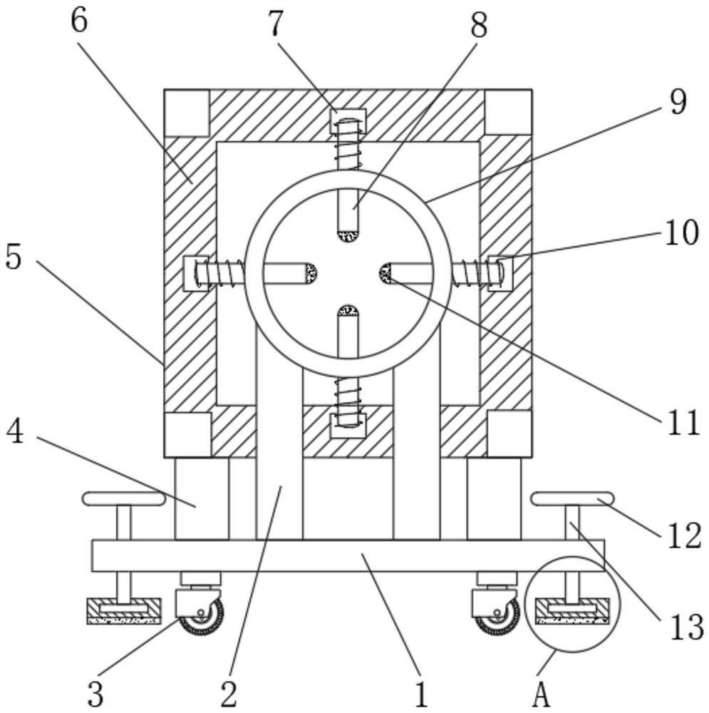
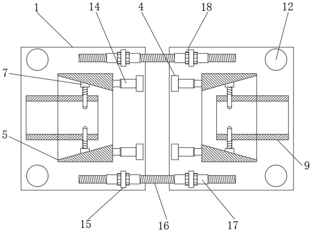
[0031] refer to Figure 1-4 , a fixing device for plastic pipe production, comprising a base plate 1, a movable frame 5 and a fixed cylinder 9, the top outer wall of the base plate 1 is welded with a support column 2, and the top outer wall of the support column 2 is welded to the bottom outer wall of the fixed cylinder 9, the base plate The top outer wall of 1 is welded with a fixed plate 4, and one side outer wall of the fixed plate 4 is connected with a hydraulic cylinder 14 by bolts, one end of the piston of the hydraulic cylinder 14 is connected with the outer wall of the movable frame 5 side by bolts, and the surrounding inner walls of the movable frame 5 are There is a chute 6, and the outer wall of the fixed cylinder 9 is provided with sliding holes, and the inner wall of the sliding hole is slidably connected with a slider 8, and the outer wall of one end of the slider 8 is welded with a slider 7, and the section of the slider 7 is a right angle. trapezoidal, the oute...

Embodiment 2

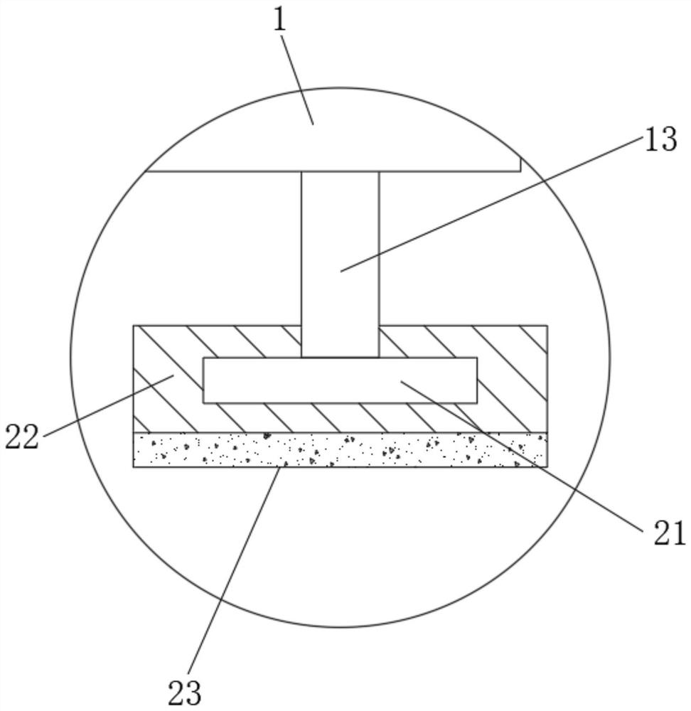
[0035] refer to Figure 5, a fixing device for plastic pipe production. Compared with Embodiment 1, this embodiment also includes a rubber block 11 with a cavity 19 inside, and a pressure sensor 20 inside the cavity 19. The pressure sensor 20 The signal output terminal is connected with the controller through the signal line, and the controller is connected with the switch through the wire.

[0036] Working principle: When in use, when the rubber block 11 is in contact with the pipe, the cavity 19 in the rubber block 11 is compressed, so that the pressure sensor 20 in the cavity 19 can detect the pressure value of the pipe, when it reaches a certain pressure value Just can send signal to controller, controller sends control signal to the switch of hydraulic cylinder 14, makes hydraulic cylinder 14 stop working, effectively avoids that the situation that plastic pipeline is crushed occurs, and use effect is better.


PUM


Abstract

The invention discloses a fixing device for plastic pipeline production, which comprises a bottom plate, a movable frame and a fixed cylinder. The top outer wall of the bottom plate is provided with a support column, and the top outer wall of the support column is welded to the bottom outer wall of the fixed cylinder. The bottom plate A fixed plate is welded on the outer wall of the top of the fixed plate, and a hydraulic cylinder is connected to one side of the fixed plate by bolts. One end of the piston of the hydraulic cylinder is connected to the outer wall of one side of the movable frame by bolts. The outer walls around the fixed cylinder are provided with slide holes, and the inner walls of the slide holes are slidably connected with a slide bar, and the outer wall of one end of the slide bar is welded with a slide block, and the section of the slide block is a right-angled trapezoid. The rubber block at the top of the sliding rod in the present invention can hold against the outer wall of the pipe and play a fast fixing role. When the pipe needs to be removed, only need to drive the hydraulic cylinder to work in reverse to make the pipe free from the restriction of the rubber block, which is very convenient to use , effectively speeding up the fixing efficiency of the device.

Description

technical field [0001] The invention relates to the technical field of plastic pipe production, in particular to a fixing device for plastic pipe production. Background technique [0002] Plastic pipe refers to the general term for pipes made of plastic materials. It has the characteristics of light weight, sanitation and safety, small water flow resistance, energy saving, metal saving, improvement of living environment, long service life, safety and convenience, etc., and is favored by the pipeline engineering industry. , Compared with traditional cast iron pipes, galvanized steel pipes, cement pipes and other pipes, plastic pipes have the advantages of energy saving and material saving, environmental protection, light weight and high strength, smooth inner wall without scaling, easy construction and maintenance, long service life, etc., and are widely used Used in building water supply and drainage, urban and rural water supply and drainage, city gas, electric power and op...

Claims


Application Information

Patent Timeline
Patent Type & Authority Patents(China)
IPC IPC(8): B26D7/02B23Q3/06
CPCB23Q3/06B26D7/02B26D2007/013
Inventor 赵艳
Owner 山东康雨管业有限公司
Why Eureka
Try Eureka