

Power distribution system and power distribution method for exhibit cars
A technology for power distribution systems and vehicle exhibitions, applied in circuits, vehicle components, electrical components, etc., can solve problems such as functional failure of electrical equipment, common impedance conduction coupling, etc., to reduce the interference of voltage fluctuations and voltage drops, and improve work performance. Reliability, avoid the effect of mechanical structure being too large
- Summary
- Abstract
- Description
- Claims
- Application Information
AI Technical Summary
Problems solved by technology
Method used
Image

Examples
Embodiment 1
[0030] The embodiment of the present invention provides a power distribution system for a show car, which can solve the technical problems that the circuit system of the show car has a common impedance conduction coupling phenomenon, and the functions of the electrical equipment are prone to sudden failure.
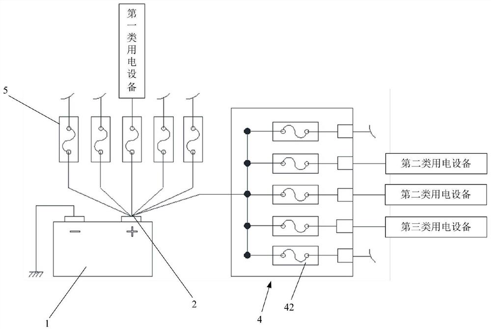
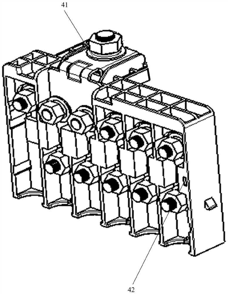
[0031] figure 1 It is a power distribution system for exhibition vehicles, including: a battery 1 , a first power-taking device 2 and a second power-taking device 4 .
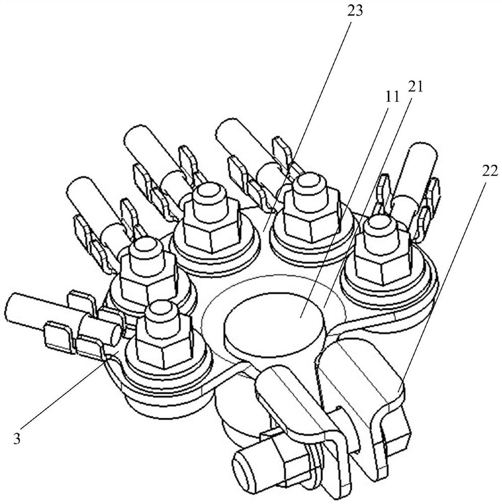
[0032] see figure 2 As shown, the first power-taking device 2 is used to connect with the positive pole 11 of the battery 1. The first power-taking device 2 is connected with a plurality of power-taking rings 3, and each power-taking ring 3 is used to connect the The first type of electrical equipment, the rated power of the first type of electrical equipment is not less than the preset power, and the first type of electrical equipment can work normally when the deviation from the voltage of the battery ...
Embodiment 2
[0037] On the basis of Example 1, as an optional implementation: see figure 2 As shown, the first power-taking device 2 includes an open sleeve 21, the open sleeve 21 is used to be socketed with the positive pole 11 of the battery 1, and the two opening sides of the open sleeve 21 are extended to form a locking end 22. A locking end 22 locks the open sleeve 21 and the positive pole 11 of the battery 1 through fasteners, the open sleeve 21 extends away from the two opening sides to form a power-taking end 23, and the power-taking end 23 is connected to a plurality of power-taking rings 3 connections. The first power-taking device 2 has a simple structure, and is connected to a plurality of power-taking rings 3, and each power-taking ring 3 is connected to a first-type power-consuming device, that is, the first-type power-consuming device is directly connected to the positive pole 11 of the battery 1. Get electricity.
Embodiment 3
[0039] On the basis of Example 1, as an optional implementation: see figure 1 As shown, a first fuse 5 is connected in series on each wire connected to the power-taking ring 3 . The first fuse 5 provides protection for the power consumption lines of the first type of power consumption equipment.
PUM
 Abstract
Description
Claims
Application Information