
Stepped shaft type part conveying mechanism

A conveying mechanism and stepped shaft technology, which is applied in the field of stepped shaft-type parts conveying mechanism, can solve the problems such as the inability of the pump head to move or tilt, and achieve the effects of improved conveying efficiency, strong controllability, and simple overall structure

Pending Publication Date: 2020-08-14
CHANGZHOU HUITUO TECH
View PDF1 Cites 0 Cited by
  • Summary
  • Abstract
  • Description
  • Claims
  • Application Information

AI Technical Summary

Problems solved by technology

[0005] The technical problem to be solved by the present invention is: in order to overcome that the conveying device in the existing packaging machine can only be used for the linear conveying of the pump head, and the pump head is moved by the friction force between the pump head and the belt during conveying, the two belts arranged in parallel One of the fifth conveying belts slipping will cause the problem that the pump head cannot move or tilt, and a stepped shaft type parts conveying mechanism is provided

Method used


Image

  • Stepped shaft type part conveying mechanism
  • Stepped shaft type part conveying mechanism
  • Stepped shaft type part conveying mechanism

Examples


Embodiment 1

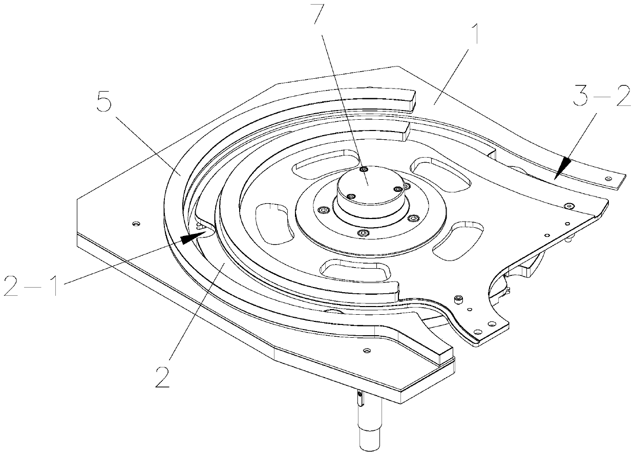
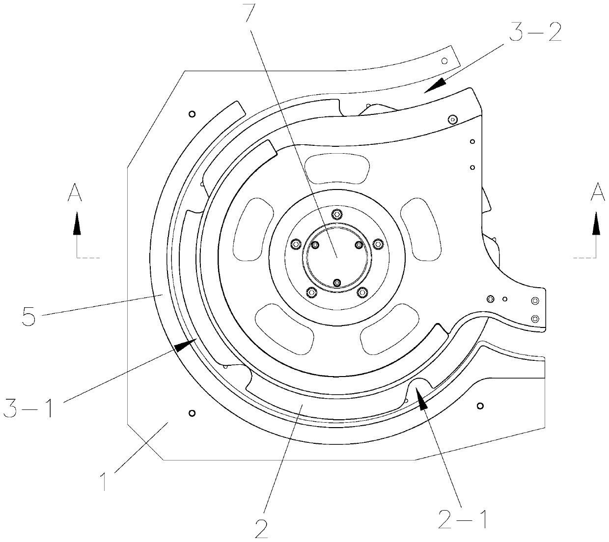
[0038] like figure 2 A stepped shaft-type parts conveying mechanism shown includes a base 1 and a moving plate 2 that rotates relatively along the base 1. The rotating shaft is installed on the base 1, and the moving plate 2 is fixedly installed on the rotating shaft, as shown in FIG. Figure 4 As shown, the base 1 is provided with a conveying guide rail for the movement of the pump head 6-3, both sides of the conveying guide rail on the base 1 are fixedly installed with limit guide rails 5, and the pump sleeve 6-1 is clamped between the two limit guide rails 5 between; the moving plate 2 is provided with a bayonet 2-1 for clamping the pump head 6-3, such as image 3 As shown, the bayonet 2-1 is a superior arc structure, the bayonet 2-1 moves out of the side of the pump head 6-3 and the moving plate 2 has an arc degree, the bayonet 2-1 has 5, and the 5 bayonets 2 -1 is evenly distributed along the circumference of the central axis of the moving plate 2, and the bayonet 2-1 i...

Embodiment 2

[0044] Compared with Embodiment 1, the difference between Embodiment 2 and Embodiment 1 is that the pressing assembly includes a slider 4-4, and the slider 4-4 is fixedly installed on the end of the claw 4-2 away from the limit plate 4-1, and the cam 4- The edge of 3 is provided with guide groove 4-3-1 in the peripheral direction, as Figure 10 and Figure 11 As shown, the slide block 4-4 is slidingly clamped in the guide groove 4-3-1, and the slide block 4-4 can always move along the edge of the cam 4-3.


PUM


Abstract

The invention relates to a stepped shaft type part conveying mechanism, and belongs to the technical field of packaging machinery. The conveying mechanism comprises a base and a moving disc relativelyrotating along the base, wherein a conveying guide rail for a pump head to move is arranged on the base, the conveying guide rail comprises a steering rail coaxial with the moving disc and an outputrail for limiting the pump head to move along with the moving disc, a bayonet used for clamping the pump head is formed in the movable disc, a clamping assembly used for vertically arranging the pumphead in the bayonet is fixedly installed on the movable disc, the movable disc rotates, the pump head enters the bayonet, the clamping assembly clamps the pump head, and the pump head moves along thesteering rail; and when the pump head enters the output rail, the clamping assembly is separated from the pump head, the pump head is moved out of the bayonet, the pump head is pushed by the moving disc, the moving disc directly provides thrust for the pump head to move along the conveying guide rail, the force transmission process is short, the conveying efficiency of the pump head is high, the overall structure is simple, the controllability is high, steering conveying of the pump head is achieved, meanwhile, the conveying efficiency of the pump head is improved, and the packaging efficiencyis improved.

Description

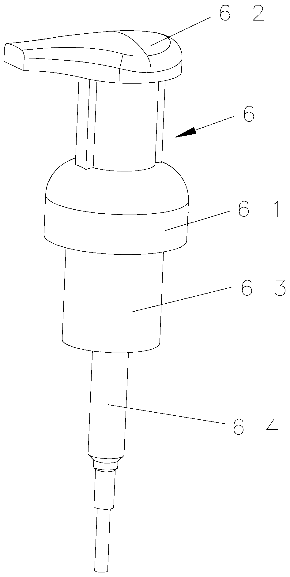
technical field [0001] The invention relates to the technical field of packaging machinery, in particular to a stepped shaft type parts conveying mechanism. Background technique [0002] The stepped shaft type parts are cylinders with different radii that are coaxially arranged up and down. The stepped shaft type parts have a wide range of applications, such as daily chemical products currently on the market, such as shampoo bottles, shower gel bottles, detergent bottles, etc. For the convenience of use, most of them adopt the form of pressing the pump head, and the liquid in the bottle is pumped out by pressing the pump head. Press the pump head to become a stepped shaft-shaped part, including a pump sleeve 6-1 for installing on the bottle mouth, a liquid outlet head 6-2 for pressing to make the liquid in the bottle flow out, and a pump head extending into the bottle 6-3 and pipette 6-4, such as figure 1 As shown, the liquid outlet head 6-2, the pump sleeve 6-1, the pump ...

Claims


Application Information

Patent Timeline
Patent Type & Authority Applications(China)
IPC IPC(8): B65B35/30B65G47/84
CPCB65B35/30B65G47/846
Inventor 段学连胡家鑫立石岩
Owner CHANGZHOU HUITUO TECH
Learn More