Anti-swinging, quakeproof and electromagnetic lifting crane

An anti-sway and crane technology, which is applied in the direction of cranes, traveling mechanisms, spring mechanisms, etc., can solve the problems of insignificant anti-sway and shock absorption effects, difficult installation, high production costs, etc., and achieve point-to-point control functions for hanging objects , increase the service life, prevent the effect of wheel derailment

Pending Publication Date: 2020-08-14
张勇
View PDF0 Cites 1 Cited by
  • Summary
  • Abstract
  • Description
  • Claims
  • Application Information

AI Technical Summary

Problems solved by technology

[0002] The traditional electromagnetic hoisting crane, the main hoisting wire rope is wound with 8 ropes or 16 ropes, the structure is complex, the manufacturing process is cumbersome, and it cannot really play the anti-shake and anti-vibration function, such as figure 1 , figure 2 As shown in the figure, the wire rope passes through the drum guide pulley, which cannot achieve the anti-shake and shock-absorbing effect
like image 3 , Figure 4 As shown, the steel wire rope is guided to the lower pulley through four sets of drum guides. Its structure is complicated, the manufacturing process is cumbersome, and it is difficult to install, especially in subsequent maintenance; and the anti-shake and shock-absorbing effect is not significant.
[0003] To sum up, the existing anti-sway and anti-vibration electromagnetic cranes have problems such as poor anti-sway and anti-vibration effects, high anti-sway costs, and inability to actually meet user requirements, high production costs, and difficult installation and maintenance.

Method used


Image

  • Anti-swinging, quakeproof and electromagnetic lifting crane
  • Anti-swinging, quakeproof and electromagnetic lifting crane
  • Anti-swinging, quakeproof and electromagnetic lifting crane

Examples


Embodiment Construction

[0033] The present invention will be further described below in conjunction with the accompanying drawings.

[0034] In order to make the object, technical solution and advantages of the present invention clearer, the present invention will be further described in detail below in conjunction with the accompanying drawings and specific embodiments. It should be understood that the specific embodiments described here are only used to explain the present invention, and are not intended to limit the present invention.

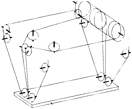
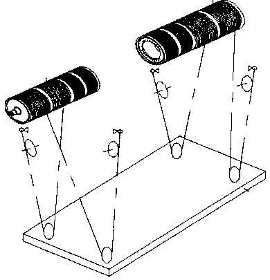
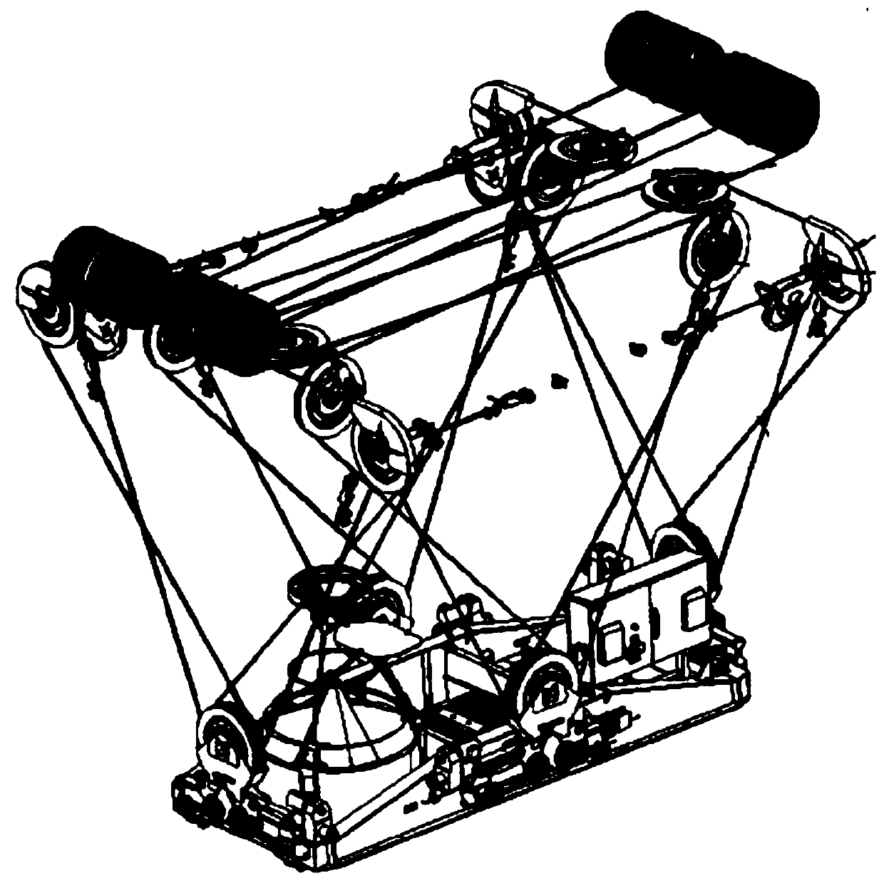
[0035] see Figure 5-10 , an anti-sway and anti-vibration electromagnetic crane, comprising a bridge frame 1 and an anti-shake and anti-vibration trolley 2, the bridge frame 1 is driven by a motor, the anti-shake and anti-vibration trolley 2 moves along the bridge frame 1, a first reel 21 is arranged on the anti-shake and anti-vibration trolley 2, and Comprising the anti-false spreader 3, the anti-false spreader 3 includes a "well"-shaped swivel frame 31, a second...


PUM


Abstract

The invention discloses an anti-swinging, quakeproof and electromagnetic lifting crane. The crane comprises a bridge and an anti-swinging and quakeproof trolley; the bridge is driven by a motor; the anti-swinging and quakeproof trolley moves along the bridge; a first drum is arranged on the anti-swinging and quakeproof trolley; the crane further comprises an anti-shaking lifting tool; the anti-shaking lifting tool comprises a #-shaped rotating frame; a second drum is arranged on the rotating frame; pulleys are arranged on all the bulging surfaces of the rotating frame; four steel wire ropes are arranged among the pulleys, the first drum and the second drum and are intertwined in a forwards, backwards, leftwards and rightwards crossing manner; the rotating frame is restrained correspondingly in the front, back, left and right directions; a rotating motor is arranged in the center of the rotating frame; and a hanging beam rotates on an output shaft of the rotating motor. The crane is simple and reasonable in structure and convenient to use, the four steel wire ropes are arranged among the pulleys, the first drum and the second drum and are intertwined in the forwards, backwards, leftwards and rightwards crossing manner, the rotating frame is restrained correspondingly in the front, back, left and right directions, and the function of preventing shaking in the four directions is realized.

Description

technical field [0001] The invention relates to the technical field of hoisting equipment, in particular to an anti-sway anti-vibration electromagnetic hoisting crane. Background technique [0002] The traditional electromagnetic hoisting crane, the main hoisting wire rope is wound with 8 ropes or 16 ropes, the structure is complicated, the manufacturing process is cumbersome, and it cannot really play the anti-shake and anti-vibration function, such as figure 1 , figure 2 As shown, the wire rope passes through the drum guide pulley, which cannot achieve the anti-shake and shock-absorbing effect. Such as image 3 , Figure 4 As shown, the steel wire rope is guided to the lower pulley through four sets of drum guides. Its structure is complicated, the manufacturing process is cumbersome, and it is difficult to install, especially in subsequent maintenance; and the anti-shake and shock-absorbing effect is not significant. [0003] To sum up, existing anti-sway and anti-vi...

Claims


Application Information

Patent Timeline
Patent Type & Authority Applications(China)
IPC IPC(8): B66C1/06B66C13/06B66C13/48B66C9/18B66D3/06B66D1/26
CPCB66C1/06B66C9/18B66C13/06B66C13/48B66C2700/08B66D1/26B66D3/06B66D2700/0183B66D2700/026
Inventor 张勇
Owner 张勇
Why Eureka
Try Eureka