
Multidirectional hydraulic vibration reduction dynamic vibration absorber structure of steel rail

A technology of vibration force and vibration absorber, which is applied in the field of multi-directional hydraulic vibration damping force vibration absorber structure, can solve the problems that small displacement and vibration reduction cannot be realized, and achieve the effect of simple structure, space saving and good vibration and noise reduction effect

Active Publication Date: 2020-08-14
SHANGHAI UNIV OF ENG SCI
View PDF28 Cites 1 Cited by
  • Summary
  • Abstract
  • Description
  • Claims
  • Application Information

AI Technical Summary

Problems solved by technology

[0006] The patent application number is 201910594773.X, a hydraulic damping piston with adjustable damping based on a guide shaft. A movable piston is set outside the piston rod, and the movable piston fits or separates from the fixed piston with the movement of the piston rod; There is a guide shaft vertically arranged at the bottom, the piston rod and the fixed piston at the end are simultaneously set outside the guide shaft, and a throttling groove is opened on the guide shaft, which is characterized by throttling and vibration reduction when the piston moves greatly. However, vibration reduction for small displacements cannot be achieved

Method used


Image

  • Multidirectional hydraulic vibration reduction dynamic vibration absorber structure of steel rail
  • Multidirectional hydraulic vibration reduction dynamic vibration absorber structure of steel rail
  • Multidirectional hydraulic vibration reduction dynamic vibration absorber structure of steel rail

Examples


Embodiment Construction

[0029] The specific implementation manner of the present invention will be described in detail below in conjunction with the accompanying drawings and preferred embodiments.

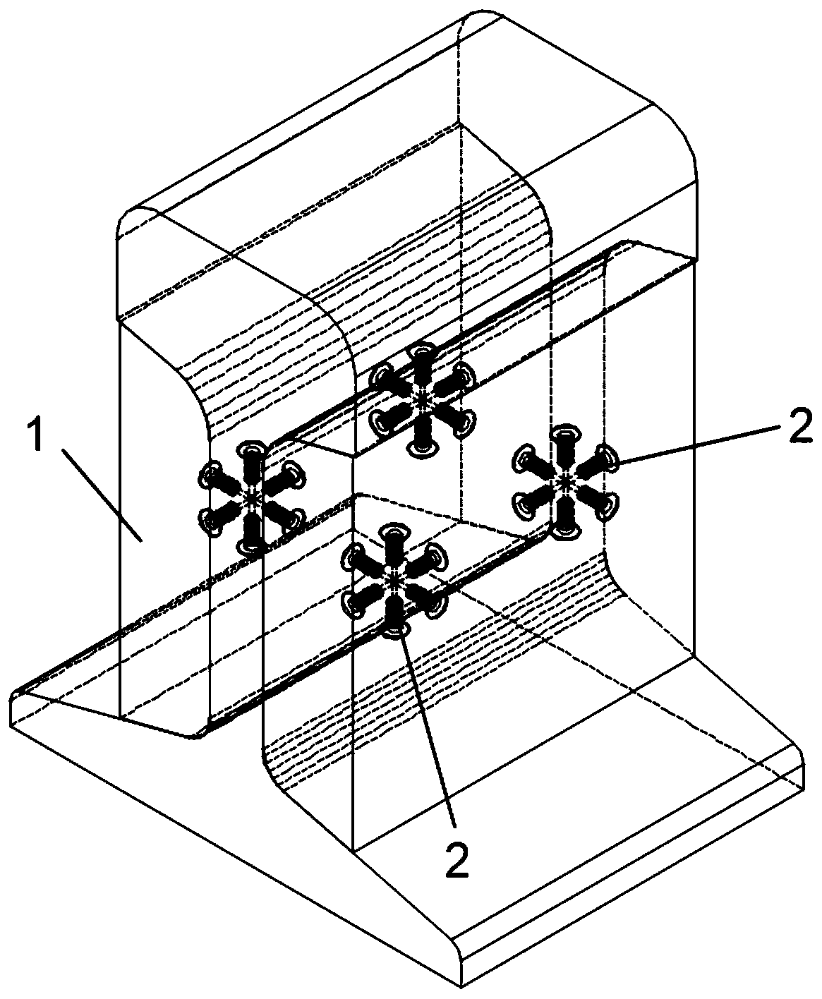
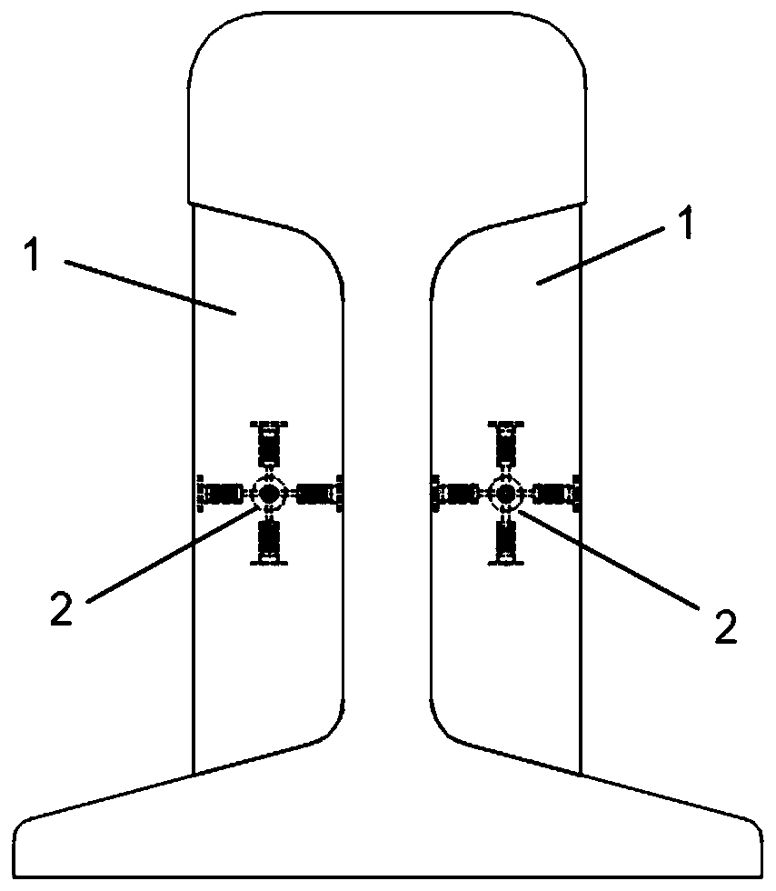
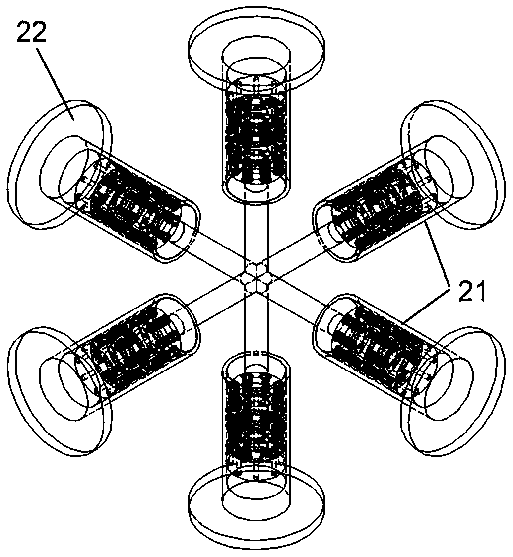
[0030] Such as figure 1 and 2 As shown, the present invention provides a multi-directional hydraulic vibration damping force absorber structure of a rail, which is arranged on both sides of the rail waist of the rail, and includes an elastic damping body 1, which is closely fixed on the rail, and its interior One or more hydraulic vibrators 2 are embedded at even intervals, all of which are wrapped by the elastic damping body 1. The hydraulic vibrator 2 includes an even number of hydraulic telescopic rods 21, which are connected together to form a spherical array structure, and they are collinear and opposite to each other. , discs 22 are arranged at the free ends of the hydraulic telescopic rods 21, such as image 3 shown. In this way, the hydraulic vibrator 2 composed of a plurality of hydraulic tel...


PUM


Abstract

The invention belongs to the technical field of vibration and noise reduction of rail transit and discloses a multidirectional hydraulic vibration reduction dynamic vibration absorber structure of a steel rail. The structure is arranged on two sides of a rail web of the steel rail. An elastic damping body is included. The elastic damping body is tightly attached and fixed to the steel rail, one ormore hydraulic vibrators are evenly embedded in the elastic damping body at intervals, each hydraulic vibrator comprises an even number of hydraulic telescopic rods, every two hydraulic telescopic rods are collinearly and oppositely connected together to form a spherical array structure, each hydraulic telescopic rod can be divided into a piston rod and a piston cylinder, and damping oil is arranged in each hydraulic telescopic rod. Vibration energy is consumed through telescopic movement of the hydraulic telescopic rod, a vertical vibration reduction effect can be achieved on a straight section of a railway, a transverse and vertical bidirectional vibration reduction effect can be realized on a curve section of the railway, and meanwhile an auxiliary anti-bending and anti-torsion effectcan be achieved.

Description

technical field [0001] The invention relates to the technical field of rail transit vibration reduction and noise reduction, in particular to a multi-directional hydraulic vibration reduction force shock absorber structure for rails. Background technique [0002] Railway transportation is one of the most convenient transportation methods today. During the operation of rail vehicles, due to the unevenness of the track, there is severe vibration between the wheel and rail. Therefore, a dynamic vibration absorber structure in which the vibrator is wrapped by a damping body came into being. A dynamic vibration absorber is a device that uses a resonance system to absorb the vibration energy of an object to reduce the vibration of the object. The principle is to attach a mass spring resonance system to the vibrating object, and the reaction force produced by this additional system during resonance can reduce the vibration of the vibrating object. Due to the simple structure of t...

Claims


Application Information

Patent Timeline
Patent Type & Authority Applications(China)
IPC IPC(8): E01B19/00
CPCE01B19/003
Inventor 文永蓬吴俊汉周月董昊亮
Owner SHANGHAI UNIV OF ENG SCI
Learn More