
Shield tunneling machine cutterhead structure with telescopic geological drills

A technology of geological drilling and shield machine, which is applied in the direction of earth drilling, mining equipment, tunnels, etc. It can solve the problems of high cost and complicated process, and achieve the effects of reducing wear rate, protecting tools and improving the efficiency of shield tunneling

Pending Publication Date: 2020-08-14
CHINA POWER CONSTR SOUTHERN CONSTR INVESTMENT CO LTD +2
View PDF0 Cites 4 Cited by
  • Summary
  • Abstract
  • Description
  • Claims
  • Application Information

AI Technical Summary

Problems solved by technology

[0004] Although the boulder treatment is an auxiliary project, the process is complex and costly. Most of the existing boulder treatment uses ground pretreatment to manually break it, and ground punching or hydraulic splitting needs to be carried out on the ground corresponding to the boulder position. Therefore, the boulder It can’t be too far from the ground, otherwise it can only be manually demolished in the hole, such as directional blasting, but manual demolition has certain construction risks. It can be seen that boulders that cannot be pretreated on the ground are still a major problem in the industry

Method used


Image

  • Shield tunneling machine cutterhead structure with telescopic geological drills
  • Shield tunneling machine cutterhead structure with telescopic geological drills
  • Shield tunneling machine cutterhead structure with telescopic geological drills

Examples


Embodiment Construction

[0026] In order to better understand the purpose, technical solution and technical effect of the present invention, the present invention will be further explained below in conjunction with the accompanying drawings and embodiments. At the same time, it is stated that the embodiments described below are only used to explain the present invention, and are not intended to limit the present invention.

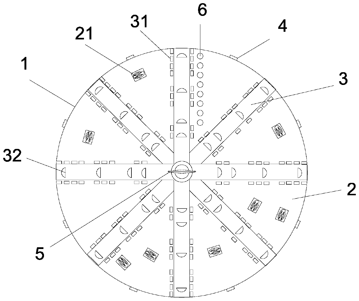
[0027] Such as figure 1 As shown, in embodiment one, a shield machine cutter head structure with a retractable geological drill includes a disc main body 1, a web plate 2 and spokes 3, and a peripheral knife 4 is provided on the circumference of the disc main body 1 for Cutting the rock and soil at the edge of the cutterhead, the spoke plate 2 is provided with a hob 21, which is used to press out circular indentations on the rock and soil, and generates lateral pressure to make the rock and soil continuously crack, and the spoke 3 is provided with a cutting knife 31. It is used t...


PUM


Abstract

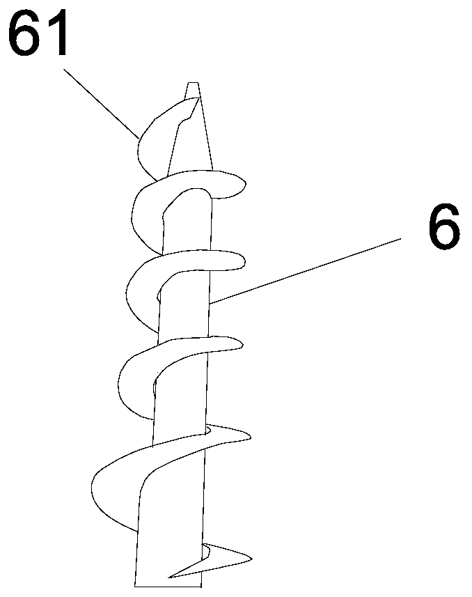
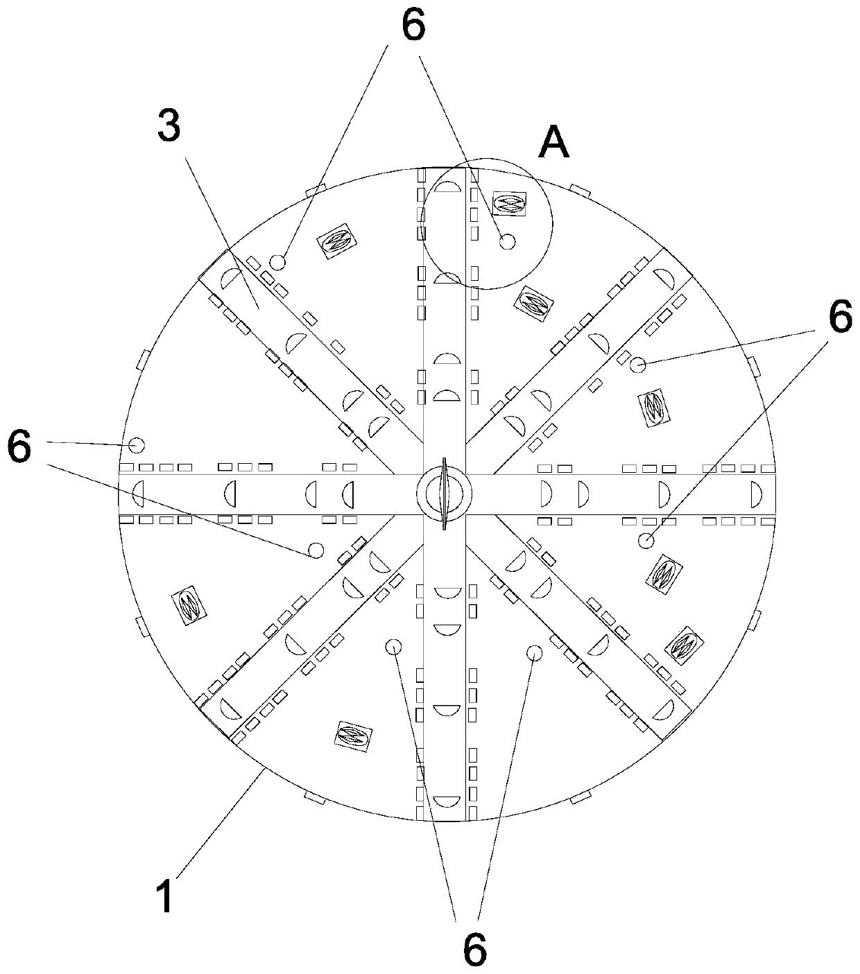
The invention relates to a shield tunneling machine cutterhead structure with telescopic geological drills. The shield tunneling machine cutterhead structure comprises a disc main body, radial platesand spokes; the periphery of the disc main body is provided with peripheral cutters, the radial plates are provided with hobbing cutters, the spokes are provided with cutters, and the edges of the spokes are provided with the multiple telescopic geological drills; when a cutterhead is rotated, motion trails of the multiple telescopic geological drills are concentric circles, the telescopic geological drills are located in cavity pipes, the openings of the cavity pipes are provided with movable plates, when the telescopic geological drills stretch out of the cavity pipes, the movable plates areopened, and when the telescopic geological drills contract into the cavity pipes, the movable plates are closed. According to the shield tunneling machine cutterhead structure, by arranging the telescopic geological drills on the cutterhead, boulder is effectively drilled into a honeycomb briquette shape, the structure and hardness of the boulder are broken, the boulder can be smashed by the cutters advantageously, accordingly, the cutters are protected, and the cutter abrasion rate is decreased; and in addition, the problem that the boulder cannot be machined on the ground is soved, and theshield driving efficiency is improved.

Description

technical field [0001] The invention relates to the field of tunnel excavation, in particular to a shield machine cutter head structure with a retractable geological drill. Background technique [0002] The shield method is the most important all-mechanical method in tunnel excavation. The shield machine is used to push the tunnel in the underground soil to form a tunnel. The front end of the shield machine is a circular cutterhead, which is used to crush the rock and soil at the front end. The segments support the surrounding rock and soil to prevent collapse. Generally, the cutter head is equipped with a center fishtail knife, a hob and a cutting knife. The center fishtail knife is located in the center of the cutter head. Compared with other tools, it is the most prominent. It can first rotate the rock and soil and drill a small circle on the rock and soil. , to facilitate the rotation of the entire cutter head; the hob is formed into a wheel shape, and the thrust makes ...

Claims


Application Information

Patent Timeline
Patent Type & Authority Applications(China)
IPC IPC(8): E21D9/08
CPCE21D9/08
Inventor 陈多谋段景川张宏伟
Owner CHINA POWER CONSTR SOUTHERN CONSTR INVESTMENT CO LTD
Learn More