A segment unloading device inside a shield machine tunnel and its working method

An unloading device and shield machine technology, applied in tunnels, mining devices, tunnel linings, etc., can solve the problems of small area range, insufficient unloading segment, slow segment unloading efficiency, etc. More diverse ways to improve work efficiency

Inactive Publication Date: 2022-02-18
许长建
View PDF6 Cites 0 Cited by
  • Summary
  • Abstract
  • Description
  • Claims
  • Application Information

AI Technical Summary

Problems solved by technology

[0004] The purpose of the present invention is to solve the problem that the segment unloading device inside the tunnel of the shield tunneling machine has a slow efficiency in unloading the segment; and the area covered by the device is small; the diversity of the device work is poor; The tightness of the clamping is poor; during the unloading of the segment by the device, the fragmented segment is too large to cause scratches and damage to the components on the device; the friction loss of the components on the unloading device is large during work, and the working Poor stability and firmness lead to poor stability and low precision of the unloading device; the unloading device is not comprehensive enough to unload segments inside the tunnel; the unloading device can only unload segments of the same diameter and width, and the adaptation of the work In view of the problem of small scope, a segment unloading device and its working method inside the shield machine tunnel are proposed

Method used


Image

  • A segment unloading device inside a shield machine tunnel and its working method
  • A segment unloading device inside a shield machine tunnel and its working method
  • A segment unloading device inside a shield machine tunnel and its working method

Examples


Embodiment Construction

[0045] The technical solutions of the present invention will be clearly and completely described below in conjunction with the embodiments. Apparently, the described embodiments are only some of the embodiments of the present invention, not all of them. Based on the embodiments of the present invention, all other embodiments obtained by persons of ordinary skill in the art without creative efforts fall within the protection scope of the present invention.

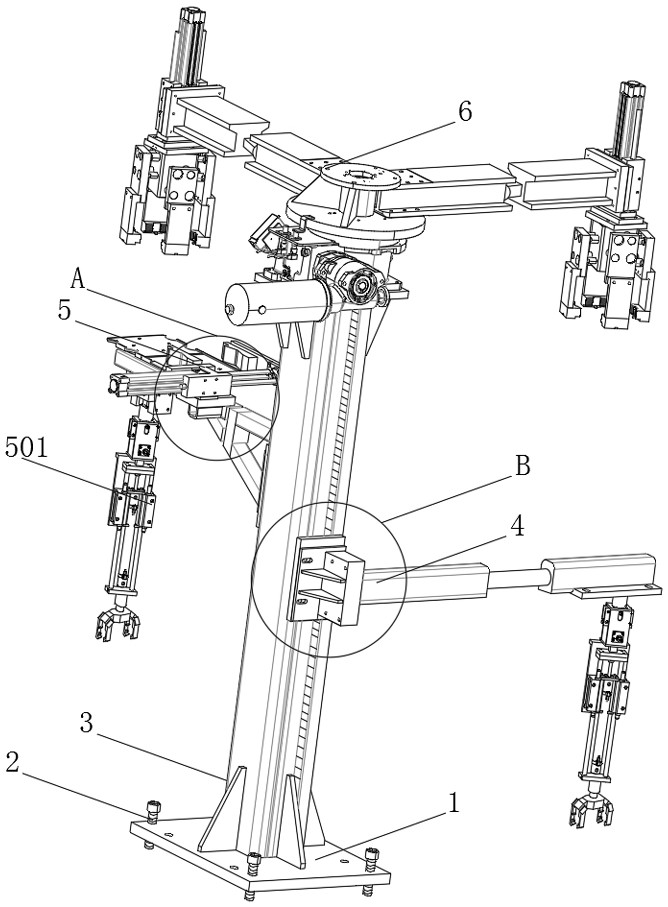
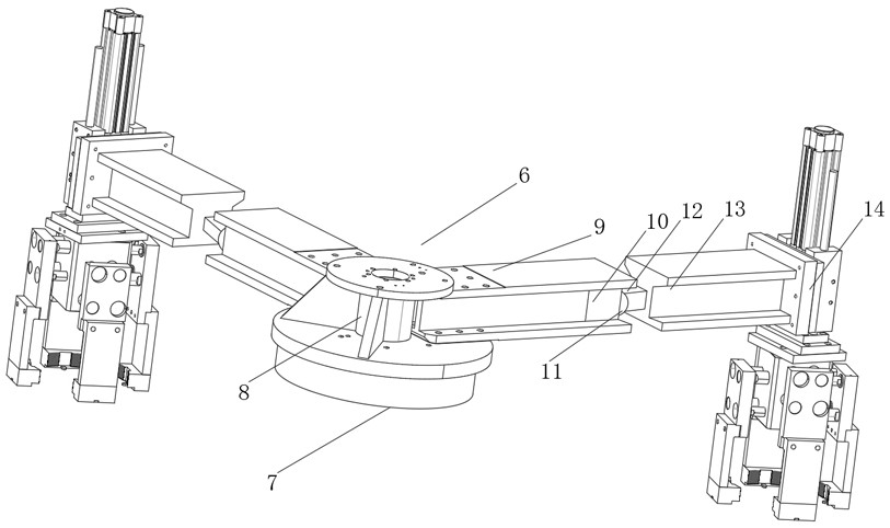
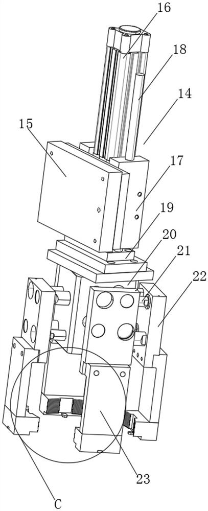
[0046] see Figure 1-12 As shown, a segment unloading device inside a shield machine tunnel includes a loading plate 1, a mounting frame 3, a right unloading platform 4, a left unloading platform 5, and a top unloading platform 6. The side wall of the loading plate 1 is provided with hanging The loading frame 3, and the two sides of the loading frame 3 are respectively provided with a right unloading platform 4 and a left unloading platform 5, one end of the loading frame 3 is provided with a top unloading platform 6, and t...


PUM


Abstract

The invention discloses a segment unloading device inside a shield machine tunnel, which comprises a loading plate, a mounting frame, a right unloading platform, a left unloading platform and a top unloading platform. The side wall of the loading plate is provided with a mounting frame. And the two sides of the loading frame are respectively provided with a right unloading platform and a left unloading platform. The beneficial effects of the present invention are: the lower clamping groove under the gripping plate buckles the segment, cooperates with several arc-shaped pressing racks arranged at equal intervals to compress the outer wall of the segment, ensuring that the segment is gripped by the gripping plate Stronger, the segment is more efficiently unloaded by the grasping and unloading seat, and the broken segment is squeezed, and the crushing is more efficient and delicate, avoiding damage to the components on the device caused by the crushed segment fragments; and In the process of stretching and adjusting the four gripping plates driven by the hydraulic pump, the two matching extension shafts are connected with the extension of the hydraulic shaft in the sleeve plate to ensure that the total carrier plate and the gripping plate are adjusted more smoothly and reliably. The gripping plate is more accurate for the socketing of the segment, and reduces the friction loss when the parts of the grabbing and unloading seat are working.

Description

technical field [0001] The invention relates to a segment dismantling device, in particular to a segment unloading device inside a shield machine tunnel and a working method thereof, belonging to the technical field of segment dismantling devices. Background technique [0002] The pipe unloading device is used more and more frequently on the shield machine. The main function of the pipe unloading device is to clamp and pull the pipes arranged in the underground tunnel to remove them, so as to improve the efficiency and smoothness of the shield machine traveling inside the tunnel. . [0003] The existing segment unloading device inside the shield machine tunnel still has many deficiencies in use. The existing segment unloading device inside the shield machine tunnel has a slow unloading efficiency for the segment, and the device can cover when it is working. The area range is small, the diversity of the device's work is poor, and the fastness of the unloading device to the c...

Claims


Application Information

Patent Timeline
Patent Type & Authority Patents(China)
IPC IPC(8): E21F17/00E21D9/06E21D11/08
CPCE21F17/00E21D9/06E21D11/08
Inventor 许长建戴亚洲其他发明人请求不公开姓名
Owner 许长建
Why Eureka
Try Eureka