Self-return plunger and plunger pump with same
A plunger pump and plunger technology, applied in the field of self-returning plunger and its plunger pump, can solve the problems of short service life, damage to plunger and return disc, etc., and achieve the effect of easy maintenance and avoidance of easy damage
- Summary
- Abstract
- Description
- Claims
- Application Information
AI Technical Summary
Problems solved by technology
Method used
Image

Examples
Embodiment 1
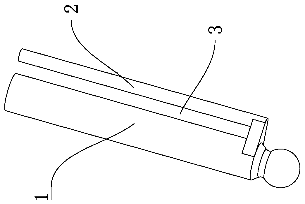
[0025] This embodiment provides a self-returning plunger, such as figure 1 As shown, the plunger body 1 is included, and the plunger body 1 is also connected with a guide rod 2 that can move synchronously with the plunger body 1. There is a gap 3 between the guide rod 2 and the plunger body 1. There is a gap 3 to facilitate the snap-in isolation structure between the plunger body 1 and the guide rod 2, so as to ensure that when inserted into the plunger pump cylinder 4, the plunger body 1 and the guide rod 2 are respectively located in two mutually isolated chambers, Thereby, the driving of the guide rod 2 is realized.
[0026] In the present invention, when in use, the hydraulic force acts on the push guide rod 2 to push the plunger body 1 back, so that there is no need to set a return plate.
[0027] Preferably, the axis line of the guide rod 2 and the axis line of the plunger body 1 are parallel to each other, and the guide rod 2 is fixedly connected or integrally formed w...
Embodiment 2
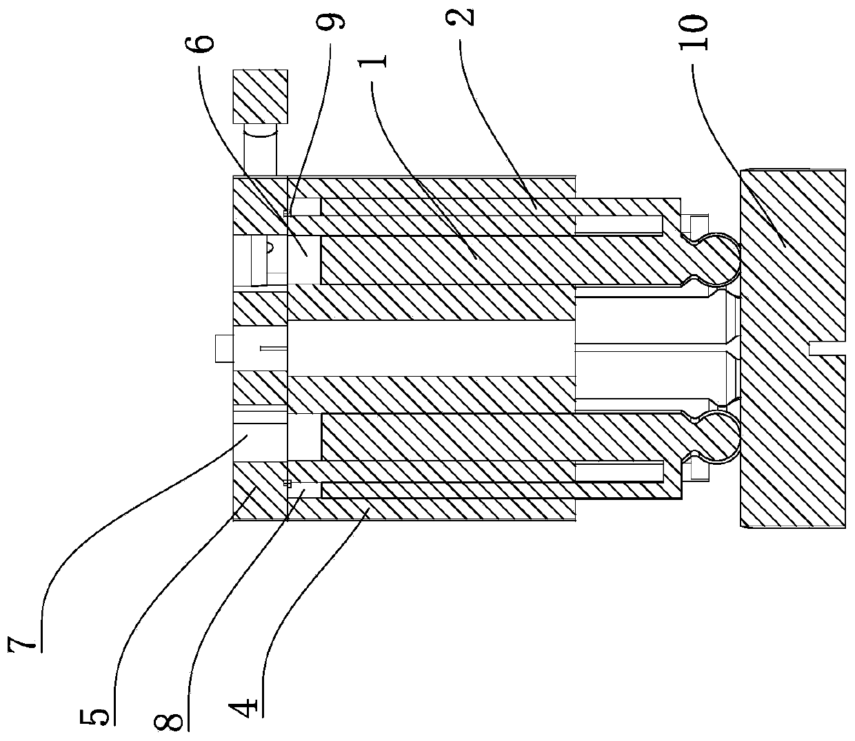
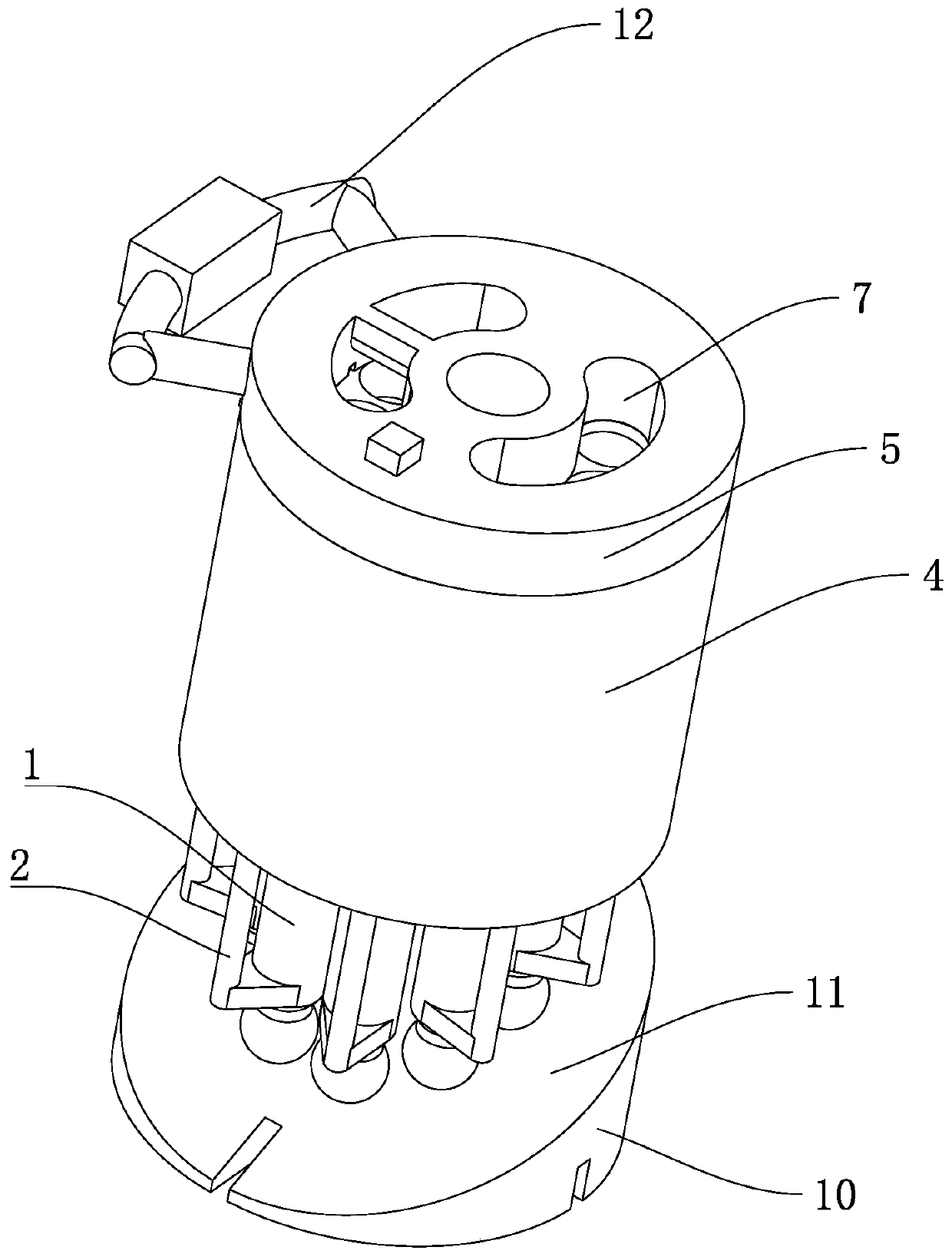
[0029] This embodiment provides a plunger pump, which adopts the self-returning plunger described in Embodiment 1, combined with Figure 1-4 As shown, it includes a plunger pump cylinder 4 with a plunger hole 6 inside and a distribution plate 5. The distribution plate 5 has a hydraulic medium flow hole 7 passing through the flow plate 5. The plunger hole 6 and the hydraulic medium flow hole 7 The plunger holes 6 are provided with several, and the plunger body 1 is slidably connected in the plunger holes 6 one by one, and the plunger pump cylinder 4 is also provided with Isolated reset hydraulic hole 8, when the plunger body 1 is inserted into the plunger pump cylinder 4, the isolation structure for isolating the plunger hole 6 and the reset hydraulic hole 8 is located in the gap 3, and the guide rod 2 is slidably connected to the Inside the reset hydraulic hole 8 , the guide rod 2 is set in one-to-one correspondence with the reset hydraulic hole 8 , and also includes a communi...
PUM
 Abstract
Description
Claims
Application Information
 - R&D Engineer
- R&D Manager
- IP Professional
- Industry Leading Data Capabilities
- Powerful AI technology
- Patent DNA Extraction
Browse by: Latest US Patents, China's latest patents, Technical Efficacy Thesaurus, Application Domain, Technology Topic.
© 2024 PatSnap. All rights reserved.Legal|Privacy policy|Modern Slavery Act Transparency Statement|Sitemap