Bearing cage segment including alignment element

A technology for bearing cages and cages, applied to bearings, bearing components, shafts and bearings, etc., can solve problems such as offset, no longer accurate alignment, segmental displacement of cages, etc., and achieve simple and reliable connection , the effect of stability improvement

Pending Publication Date: 2020-08-14
AB SKF
View PDF0 Cites 2 Cited by
  • Summary
  • Abstract
  • Description
  • Claims
  • Application Information

AI Technical Summary

Problems solved by technology

[0005] However, during production of the welded connection there is the risk that the cage segments are displaced relative

Method used


Image

  • Bearing cage segment including alignment element
  • Bearing cage segment including alignment element
  • Bearing cage segment including alignment element

Examples


Embodiment Construction

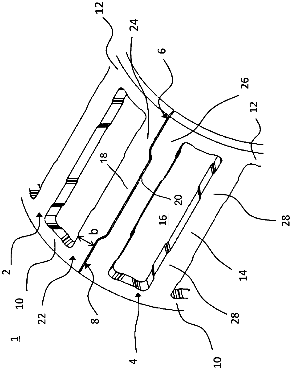
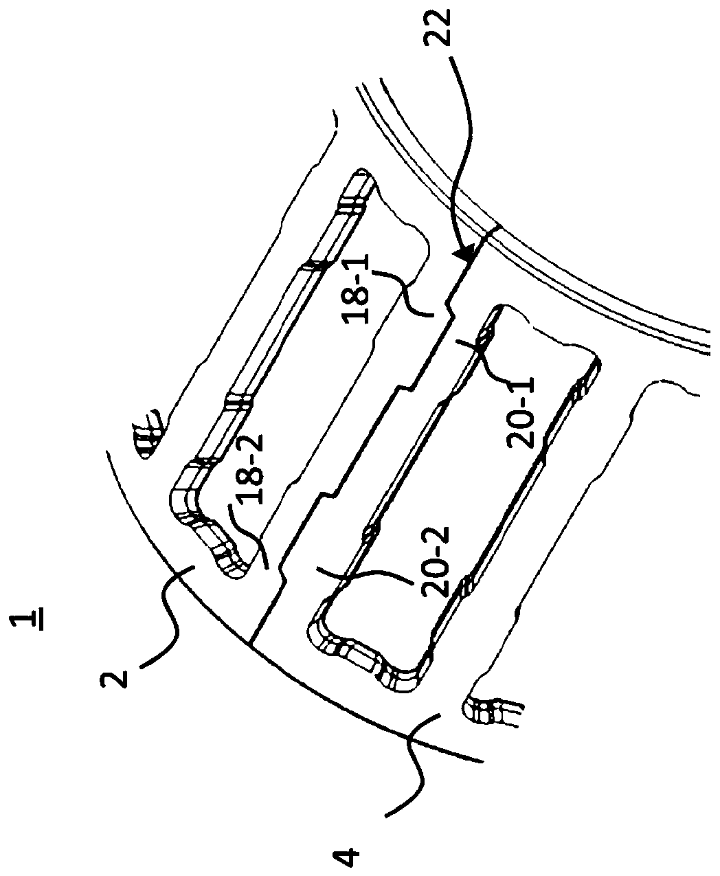
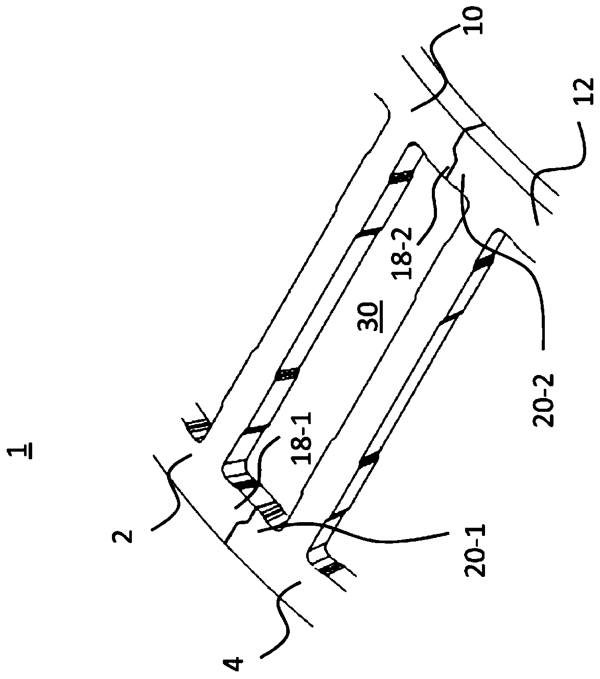
[0049] figure 1 Shows a detail view of a first exemplary embodiment of a sheet metal cage (sheet metal cage) 1 comprising a first bearing cage segment ( / segment / section) (segment) 2 and The second bearing cage segment 4 , the first bearing cage segment 2 and the second bearing cage segment 4 are arranged to abut each other at joint edges 6 , 8 , respectively. Here, instead of the first bearing cage segment 2 and the second bearing cage segment 4 , it is also possible to provide only a single bearing cage segment 2 , which comprises the joint edge 6 at the first end and the joint edge 6 at the second end. The edge of the joint at 8.

[0050] For the sake of simplicity it is assumed in the following that the metal cage comprises at least two bearing cage segments 2 , 4 abutting against each other.

[0051] Each bearing cage segment 2, 4 comprises a first ring part 10, a second ring part 12 and a plurality of bridges 14 connecting the first ring part 10 and the second ring part...


PUM


Abstract

The invention discloses a bearing cage segment (2;4) of a sheet metal cage (1) and a sheet metal cage comprising the same. In particular, the bearing cage segment is used for needle roller bearings. The bearing cage segment of a sheet metal cage includes first and second ring sections (10, 12) and a plurality of bridges (14), which are used for connecting the first ring sections and the second ring sections and defining a plurality of pockets (16) for receiving at least one rolling element. The bearing cage segment comprises at least one first joint edge (6; 8), which points to the circumferential direction and is configured to connect to a second joint edge (6; 8), and the bearing cage segment includes an alignment element (18; 20), which is configured to align the first joint (6; 8) edgeradially, axially and/or circumferentially against the second joint edge (6; 8).

Description

technical field [0001] The invention relates to a bearing cage segment of a sheet metal cage according to the preamble of claim 1 . Furthermore, the invention relates to a sheet metal cage comprising such a bearing cage segment. Background technique [0002] Bearing cages are known from the prior art which consist of one or more circular cage segments made of sheet metal, respectively at their joint edges ( / joint edges) ( joint edge), such as by welding. [0003] Here, it is known to produce the structure and contour of such bearing cage segments by punching and stamping. For this purpose, in a first step the metal strip is moved intermittently in the longitudinal direction, wherein transversely extending slots are formed by punch presses. In a further step, the metal strip is cut to length using a cross-cutting device, thereby forming a ladder-shaped sheet metal part, wherein the "rungs" of the part form bridges for the bearing cage segments, the part The slots form the...

Claims


Application Information

Patent Timeline
IPC IPC(8): F16C33/50F16C33/54
CPCF16C33/502F16C33/541F16C33/548F16C33/4694F16C33/543F16C33/545F16C2220/60F16C2226/36F16C2226/70F16C33/467
Inventor 汉斯-尤尔根·弗雷德里希诺伯特·休恩托马斯·克特纳曼弗雷德·马特斯哈拉尔德·梅茨阿希姆·穆勒阿尔弗雷德·拉迪纳乔纳斯·席灵马克西米利安·索尔纳马库斯·沃尔克姆斯
Owner AB SKF
Why Eureka
Try Eureka