Method and device for handling drink containers

Active Publication Date: 2014-02-18
KRONES AG
View PDF31 Cites 1 Cited by
  • Summary
  • Abstract
  • Description
  • Claims
  • Application Information

AI Technical Summary

Benefits of technology

[0009]The object of the present invention is therefore to reduce the stoppage times, in particular in the case of a change in the production progr

Problems solved by technology

In this case the problem arises that losses in production time arise in the event of a change of product or even a change of rolls.
On the other hand, however, magazines or conveying units of such size are difficult, in particular in the event of a change in the production programme in the line, since large magazin

Method used


Image

  • Method and device for handling drink containers
  • Method and device for handling drink containers

Examples


Embodiment Construction

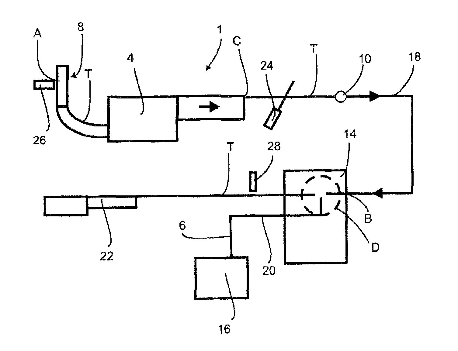
[0040]FIG. 1 is an illustration in the manner of a block diagram of an apparatus 1 according to the invention for handling containers 10. The apparatus 1 shown in FIG. 1 is a plant which provides filled bottles with labels. This illustration is to be understood, however, as being by way of example and is also capable of being applied to other apparatus which handle or equip containers in a pre-set manner, such as for example closing means, filling plants, disinfection devices and the like.

[0041]The reference sign T relates to a conveying path along which the containers already filled in this case are conveyed. In an accumulation area 4 a plurality of rows of containers 10 are conveyed adjacent to one another. The arrows indicated in FIG. 1 show the conveying direction. In the case of the embodiment shown in FIG. 1 the containers 10 are moved from a multiplicity of paths or wider paths to fewer paths or narrower paths. It is also possible, however, for the individual paths to be arra...


PUM

PropertyMeasurementUnit
Areaaaaaaaaaaa
Residual entropyaaaaaaaaaa

Abstract

A method and a device for handling containers is described, wherein the containers are transported along a predetermined transport path and combined with at least one other product, the amount of which can be determined, in such a way that the product is fed to each individual container in a predetermined feed area of the transport path, wherein the other product is routed along a feed path to the feed area. At least one characterizing state is determined in a detection area disposed upstream relative to the feed area in a direction of transport of the containers, the state being characteristic of a number of containers fed, and a residual amount for the product that remains to be fed to the predetermined feed area until the product is switched is determined as a function of this characteristic state.

Description

FIELD OF THE INVENTION[0001]The present invention relates to a method and an apparatus for handling containers, in particular containers for beverages.BACKGROUND OF THE INVENTION[0002]It is known from the prior art that in the framework of a production and filling process for containers these containers are handled in widely differing ways and further elements are attached to these bottles, such as for example labels or closures, or a beverage is also poured into them. In this case it is frequently customary that at the beginning of a process it is established how many containers will be produced and in the framework of the method the attempt is made to use the correct amounts of material for this. The material is supplied to the machines in filling and packaging lines in such a way that all the products to be processed are conveyed from a magazine to the location of the processing by way of a conveying unit which has a specified reservoir. This applies in particular for all countab...

Claims


Application Information

Patent Timeline
IPC IPC(8): B67C3/00B65B57/00
CPCB65B59/00B65B57/00B67C3/007B67C3/02B65B59/001
Inventor HASLER, UWEMAYER, JOSEFZOELFL, MARKUSHEIMANN, NORBERTRAITH, JOSEF
Owner KRONES AG
Why Eureka
Try Eureka