Non-destructive testing device and non-destructive testing method

A non-destructive testing technology to be tested, which is applied to measuring devices, instruments, and the use of sound waves/ultrasonic waves/infrasonic waves to analyze solids, etc. It can solve problems such as equipment damage and affecting the performance of non-destructive testing equipment

Active Publication Date: 2021-08-10
HEFEI INSTITUTES OF PHYSICAL SCIENCE - CHINESE ACAD OF SCI
View PDF1 Cites 0 Cited by
  • Summary
  • Abstract
  • Description
  • Claims
  • Application Information

AI Technical Summary

Problems solved by technology

For example, the minimum operating temperature of an existing non-destructive testing equipment is minus 40°C, if the temperature is lower than the minimum operating temperature, it will affect the performance of the non-destructive testing equipment, and even cause permanent damage to the equipment

Method used


Image

  • Non-destructive testing device and non-destructive testing method
  • Non-destructive testing device and non-destructive testing method
  • Non-destructive testing device and non-destructive testing method

Examples


no. 1 example

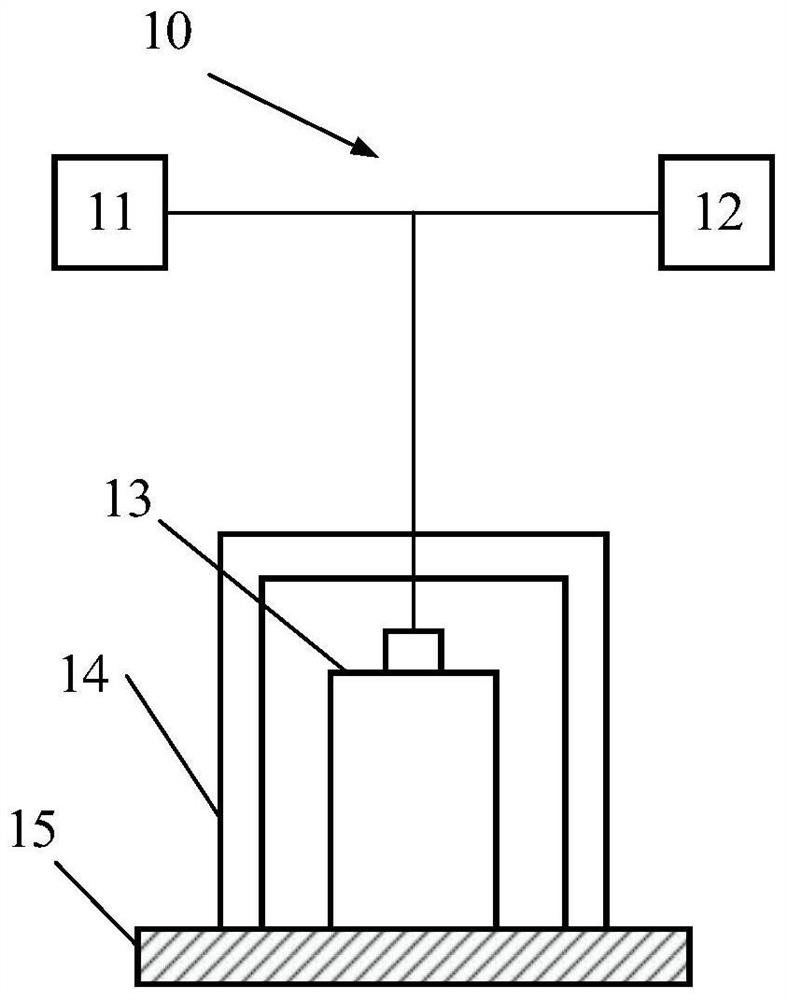
[0027] figure 1 is a schematic diagram of a non-destructive testing device according to an embodiment of the present invention.

[0028] An application scenario of the non-destructive testing device 10 according to the embodiment of the present invention is to perform non-destructive testing on the workpiece 15 to be tested (such as a superconducting magnet or a superconducting conductor), especially at a low temperature (for example, at a temperature of 4K to 200K ) for non-destructive testing.

[0029] Such as figure 1 As shown, the non-destructive testing device 10 according to the first embodiment of the present invention includes an excitation part 11 , a collection part 12 and a probe 13 , wherein both the excitation part 11 and the collection part 12 are connected to the probe 13 .

[0030] The "connection" mentioned in this article includes not only a physical wired connection, but also a direct or indirect, wired or wireless connection between two or more devices an...

no. 2 example

[0067] The second embodiment of the present invention will be described below with reference to the accompanying drawings.

[0068] The difference from the first embodiment is that the second embodiment of the present invention uses electromagnetic detection. In the following description, the same reference numerals are used for the same components as those of the first embodiment, and the description of the same or similar structures or functions as those of the first embodiment will be appropriately omitted to avoid unnecessary repetition.

[0069] The non-destructive testing device 10 according to the second embodiment of the present invention includes an excitation part 11 , an acquisition part 12 and a probe 13 , wherein both the excitation part 11 and the acquisition part 12 are connected to the probe 13 . The second embodiment of the present invention adopts electromagnetic detection technology to realize non-destructive detection. The probe 13 is an electromagnetic prob...


PUM


Abstract

Embodiments of the present invention relate to a nondestructive testing device and a nondestructive testing method. Among them, a non-destructive testing device includes: an excitation component, a collection component and a probe, the excitation component is connected to the probe and provides energy to the probe; the probe transmits a first signal to the workpiece to be detected and receives the The second signal corresponding to the first signal; the acquisition component is connected to the probe, and collects the first signal and the second signal from the probe; wherein, the non-destructive testing device also includes a probe peripheral The probe peripheral component surrounds the probe, thereby forming a first space on the periphery of the probe that isolates the probe from the external environment. According to the embodiments of the present invention, simple and easy non-destructive testing suitable for low-temperature environments, such as non-destructive testing of superconducting magnets, can be realized.

Description

technical field [0001] The invention relates to the technical field of low-temperature detection, in particular to a non-destructive testing device and a non-destructive testing method applied in the technical fields of fusion, accelerator engineering, high-temperature superconductivity and aerospace. Background technique [0002] Nuclear fusion energy is an energy source that uses nuclear fusion reactions to generate energy. It has the characteristics of safety, cleanliness, and almost unlimited energy. It plays an important role in the national science and technology development plan. One of the foundations of magnetic confinement fusion technology lies in superconducting magnet technology, and superconducting magnets usually need to work under extreme conditions. For example, superconducting magnets used in magnetic confinement nuclear fusion devices may need to maintain a superconducting state under the extreme conditions of a temperature of several kelvins, a current of...

Claims


Application Information

Patent Timeline
Patent Type & Authority Patents(China)
IPC IPC(8): G01N29/04G01N29/24G01N27/72
CPCG01N29/04G01N29/24G01N27/72G01N2291/0234G01N29/069G01N29/043G01N29/11Y02E30/10
Inventor 刘小川秦经刚周超武玉李建刚
Owner HEFEI INSTITUTES OF PHYSICAL SCIENCE - CHINESE ACAD OF SCI
Why Eureka
Try Eureka