Clamp for detecting PCB

A PCB circuit board and fixture technology, applied in the direction of electronic circuit testing, printed circuit testing, measuring device casing, etc., can solve the problems of difficult PCB circuit board detection, inconvenient operation, complicated layout, etc., and achieve the effect of rapid flipping

Inactive Publication Date: 2020-08-14
龙岩市远尚工贸有限公司
View PDF0 Cites 4 Cited by
  • Summary
  • Abstract
  • Description
  • Claims
  • Application Information

AI Technical Summary

Problems solved by technology

[0003] The PCB circuit board is generally a square structure, and the on-off detection of the circuit on the board must be carried out before it is put into use, so as not to fail to work due to the problem of the circuit board itself after the product is completed. The best method is to manually control the position of the PCB circuit board, and then the probe head is in contact with the PCB circuit board, and the operation is inconvenient. Turning over, resulting in time-consuming and labor-intensive fixing of the PCB circuit board, and it is not easy to quickly detect the bottom of the PCB circuit board

Method used


Image

  • Clamp for detecting PCB
  • Clamp for detecting PCB
  • Clamp for detecting PCB

Examples


Embodiment 1

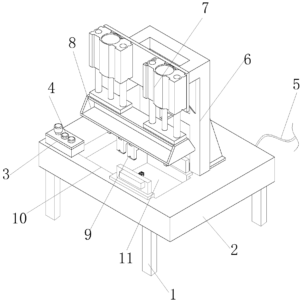
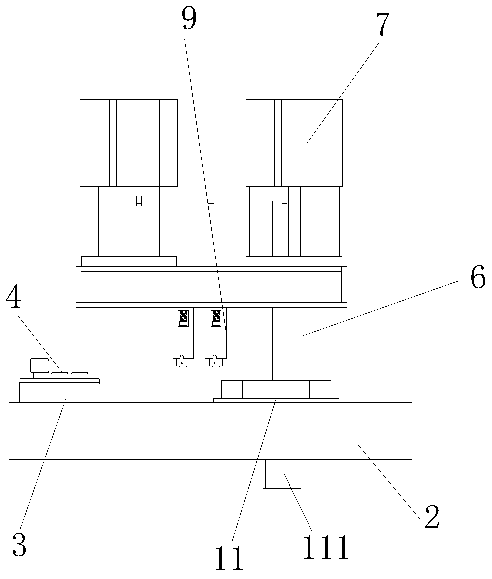
[0033] see figure 1 and figure 2 , the present invention provides a fixture for PCB circuit board detection through improvement, including a support foot 1, a fixed frame 2, a first cylinder 7, a pressure plate 8, a fixed groove 10, and a pushing mechanism 11, and the support foot 1 and the fixed frame 2. The four corners of the bottom are welded and fixed. A control panel 3 is arranged on the left front end of the top of the fixed frame 2. A button 4 is arranged on the top of the control panel 3. A power wire 5 is fixed on the rear end of the fixed frame 2. The turning mechanism 11 is installed and fixed on the front end of the fixed frame 2, the support column 6 is locked and fixed with the rear end of the first cylinder 7 by screws, the first cylinder 7 is fixedly connected to the top of the pressure plate 8, and the left and right sides of the bottom of the pressure plate 8 are oppositely provided with detection The head 9 and the front end of the top of the supporting f...

Embodiment 2

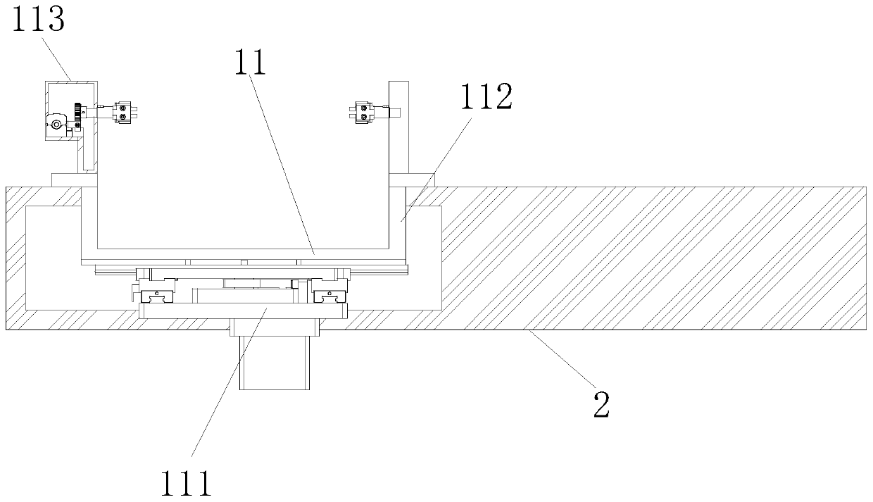
[0040] The present invention provides a fixture for PCB circuit board detection through improvement. The upper end of the guide frame 1117 is provided with a chute 1171, and the chute 1171 is in the shape of a "U". To guide the positioning shaft 1114, there are two installation frames 1131, and the installation frames 1131 are symmetrically distributed along the left and right sides of the upper end of the sliding frame 112, and the upper ends of the two installation frames 1131 are provided with gripper mechanisms 1134, It is beneficial to play the role of clamping and fixing the PCB circuit board.

[0041] The present invention provides a fixture for PCB circuit board detection through improvement, and its working principle is as follows;

[0042] First, before use, place the jig for PCB circuit board testing horizontally, so that the supporting feet 1 can fix and support the jig;

[0043] Second, when in use, connect the external power supply through the power wire 5 to pr...


PUM


Abstract

The invention discloses a clamp for PCB detection. The clamp comprises supporting legs, a fixed frame, a first air cylinder, a pressing plate, a fixing groove and a pushing turnover mechanism. According to the invention, a moving mechanism is arranged in the fixed frame; a motor drives a swing rod to swing on the inner side of a sliding groove through a positioning shaft, so that the positioningshaft drives a sliding plate to move towards the left end through a sliding rod; the sliding plate drives the PCB to be located at the bottom of a detection head through a sliding frame for detection,and the advantage that the PCB can be rapidly conveyed to a detection area is achieved; a rack linkage mechanism is arranged in a connecting frame; a second air cylinder extends towards the front end; a rack is driven by a connecting piece to move towards the inner side of a guide rail, so that the rack drives a rotating shaft to rotate through a gear; the PCB at the upper end of a clamping jaw mechanism is driven to turn over, and the advantage that the PCB can be turned over quickly is achieved.

Description

technical field [0001] The invention relates to the related field of PCB circuit board detection, in particular to a fixture for PCB circuit board detection. Background technique [0002] PCB circuit board, also known as printed circuit board, is a provider of electrical connections for electronic components; its design is mainly layout design; the main advantage of using circuit boards is that it greatly reduces wiring and assembly errors, and improves the level of automation and production labor. Rate. [0003] The PCB circuit board is generally a square structure, and the on-off detection of the circuit on the board must be carried out before it is put into use, so as not to fail to work due to the problem of the circuit board itself after the product is completed. The best method is to manually control the position of the PCB circuit board, and then the probe head is in contact with the PCB circuit board, and the operation is inconvenient. Turning over will result in t...

Claims


Application Information

Patent Timeline
Patent Type & Authority Applications(China)
IPC IPC(8): G01R31/28G01R1/04
CPCG01R1/04G01R31/2808
Inventor 林贵秀
Owner 龙岩市远尚工贸有限公司
Why Eureka
Try Eureka