Cutter control device and control method

A control device and control method technology, applied in the field of numerical control, can solve the problems of lower production efficiency, misjudgment of tool quality, increase of labor costs, etc., and achieve the effect of improving production efficiency and accuracy

Inactive Publication Date: 2020-08-14
SHENZHENSHI YUZHAN PRECISION TECH CO LTD
View PDF9 Cites 3 Cited by
  • Summary
  • Abstract
  • Description
  • Claims
  • Application Information

AI Technical Summary

Problems solved by technology

However, many factories usually detect the wear and service life of the tool manually. Due to manual errors or errors that cannot be detected by the naked eye, it is easy to cause misjudgment of the quality of the tool, which not only increases labor costs, but also increases the risk of processing errors. , leading to reduced production efficiency

Method used


Image

  • Cutter control device and control method
  • Cutter control device and control method
  • Cutter control device and control method

Examples


Embodiment Construction

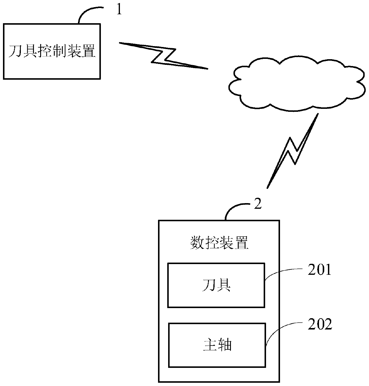
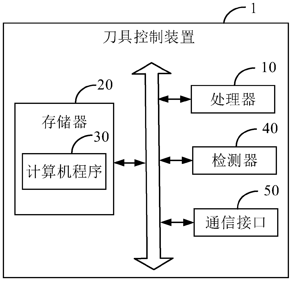
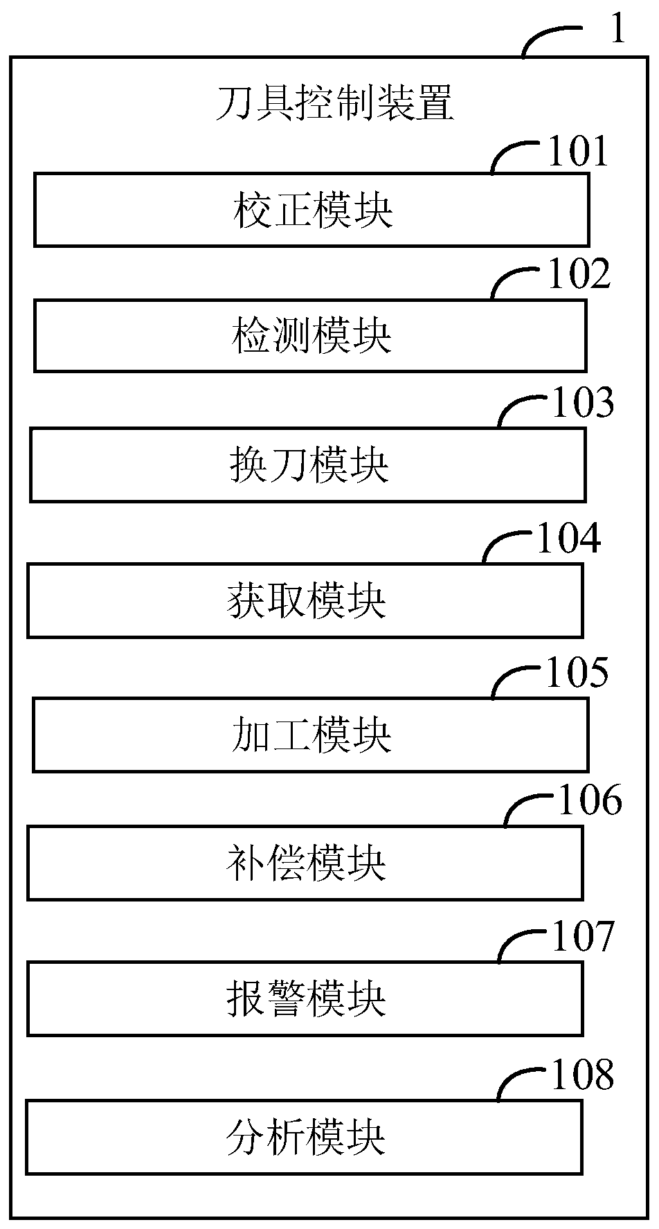
[0096] The following will clearly and completely describe the technical solutions in the embodiments of the application with reference to the drawings in the embodiments of the application. Apparently, the described embodiments are only some of the embodiments of the application, not all of them. Based on the embodiments in this application, all other embodiments obtained by persons of ordinary skill in the art without making creative efforts belong to the scope of protection of this application.

[0097] Unless otherwise defined, all technical and scientific terms used herein have the same meaning as commonly understood by one of ordinary skill in the technical field to which this application belongs. The terms used herein in the specification of the application are only for the purpose of describing specific embodiments, and are not intended to limit the application.

[0098] Some implementations of the present application will be described in detail below in conjunction wit...


PUM


Abstract

The application provides a cutter control method which comprises the steps: acquiring first parameters that are formed by detecting a first cutter and comprise at least one of the service life, the cutter breaking condition and the tipping condition of the first cutter; according to the first parameters, sending out a control instruction to control the first cutter to machine a workpiece; acquiring second parameters that are formed by detection when the first cutter processes the workpiece and comprise at least one of a length lengthening condition, a length abrasion condition, a radial abrasion condition and a blade thickness abrasion condition; and according to the blade thickness abrasion condition, sending out a compensation instruction so as to carry out position compensation on the first cutter. The invention further provides a cutter control device. According to the application, the accuracy of cutter quality detection is effectively improved, and the production efficiency is improved.

Description

technical field [0001] The present application relates to the technical field of numerical control, in particular to a tool control device and a control method. Background technique [0002] With the development of industrial technology, CNC (Computerized Numerical Control, computer numerical control) equipment has been widely used in industrial production. CNC equipment is equipped with cutting tools for processing workpieces, materials and other products. Due to the high quality requirements for product processing, the quality control of cutting tools is becoming more and more important. However, many factories usually detect the wear and service life of the tool manually. Due to manual errors or errors that cannot be detected by the naked eye, it is easy to cause misjudgment of the quality of the tool, which not only increases labor costs, but also increases the risk of processing errors. , leading to reduced production efficiency. Contents of the invention [0003] ...

Claims


Application Information

Patent Timeline
Patent Type & Authority Applications(China)
IPC IPC(8): G05B19/19
CPCG05B19/19G05B2219/35349G05B2219/37252G05B19/4065G05B19/404G05B2219/50276G05B2219/50313B23Q17/0909B23Q17/0914B23Q17/0995
Inventor 许兴智易照耀朱蕾张昌立马二羊林志升谢丰罗名涛
Owner SHENZHENSHI YUZHAN PRECISION TECH CO LTD
Why Eureka
Try Eureka