
Lower limb traction device for preventing valgus of feet

A traction device and foot eversion technology, which are applied in the fields of medical science, fractures, passive exercise equipment, etc., can solve the problems of leg exercise, simple structure, and foot eversion of patients who cannot, and achieve the effect of easy disassembly and replacement

Pending Publication Date: 2020-08-18
XIEHE HOSPITAL ATTACHED TO TONGJI MEDICAL COLLEGE HUAZHONG SCI & TECH UNIV
View PDF1 Cites 2 Cited by
  • Summary
  • Abstract
  • Description
  • Claims
  • Application Information

AI Technical Summary

Problems solved by technology

[0006] The purpose of the present invention is to provide a lower limb traction device that prevents foot valgus, to solve the problem that the existing lower limb traction device is not provided with a foot fixation device, causing the patient's foot to be valgus during the traction process, and now Some lower limb traction devices only have a simple traction function, simple structure, and can not exercise the patient's legs.
[0008] In order to realize the above-mentioned lower limb traction device for preventing foot valgus, the existing lower limb traction device is not equipped with a sole fixation device, which causes the patient's foot to appear valgus during the traction process, and the existing lower limb traction device only has Simple traction function, simple structure, inadequacy of not being able to exercise the patient's legs, the present invention provides the following technical solutions:

Method used

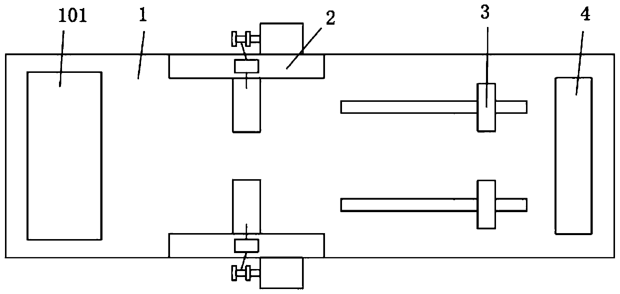
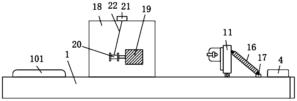
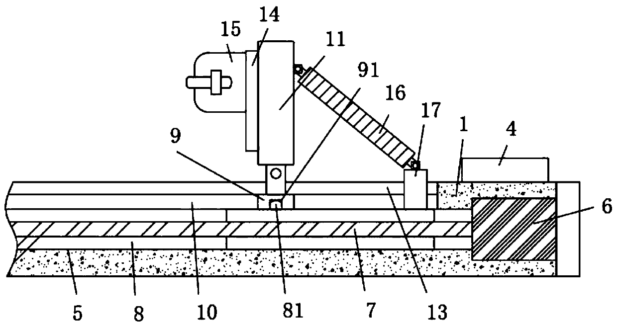

Image

  • Lower limb traction device for preventing valgus of feet
  • Lower limb traction device for preventing valgus of feet
  • Lower limb traction device for preventing valgus of feet

Examples


Embodiment Construction

[0031] The following will clearly and completely describe the technical solutions in the embodiments of the present invention with reference to the accompanying drawings in the embodiments of the present invention. Obviously, the described embodiments are only some, not all, embodiments of the present invention. Based on the embodiments of the present invention, all other embodiments obtained by persons of ordinary skill in the art without creative efforts fall within the protection scope of the present invention.

[0032] Such as Figure 1-8 A lower limb traction device for preventing foot valgus is shown, consisting of figure 1 and figure 2 As shown, including a mounting plate 1, one end of the upper surface of the mounting plate 1 is adhesively connected with a sponge cushion layer 101, and both sides of the middle of the upper surface of the mounting plate 1 are provided with a lifting assembly 2, and the other end of the upper surface of the mounting plate 1 is two Bot...


PUM


Abstract

The invention discloses a lower limb traction device for preventing the valgus of feet. The device comprises a mounting plate, one end of the upper surface of the mounting plate is connected with a sponge cushion layer in a bonding manner; pulling-up assemblies are arranged on the two sides of the middle of the upper surface of the mounting plate correspondingly, traction assemblies are arranged on the two sides of the other end of the upper surface of the mounting plate correspondingly, a controller is fixedly connected to the other end of the upper surface of the mounting plate, a limiting groove is formed in the other side of the mounting plate, and a first motor is arranged at one end of the limiting groove. According to the invention, the traction assembly is arranged on the mountingplate; a traction plate on the traction assembly can play a traction role on the legs of the patient; the detachable attaching plate is arranged on the traction plate, the coating sleeve on the attaching plate can fix the feet of a patient, the situation that the feet of the patient are turned outwards to form a splayed shape in the traction process is avoided, when the coating sleeve is damaged,the attaching plate is convenient to detach and replace, and the working efficiency of the device is not affected.

Description

technical field [0001] The invention relates to the technical field of traction devices, in particular to a lower limb traction device for preventing foot eversion. Background technique [0002] Traction plays an important role in the treatment of lower extremity fractures. It is suitable for conservative treatment of lower extremity fractures, or to maintain the length and axis of the lower extremity before surgical treatment. The way of traction is: when the patient undergoes foot and ankle surgery, after the ankle joint is fixed with an ankle sleeve, the ankle sleeve is pulled by the traction rope to achieve the purpose of pulling the joint gap. The traction rope needs a support device as a support during traction. [0003] The Chinese patent whose publication number is CN108553211A discloses a lower limb traction frame, which is composed of a mounting frame, a leg support frame and a gravity traction device, and is conveniently fixed on the On the bedside of the hospita...

Claims


Application Information

Patent Timeline
Patent Type & Authority Applications(China)
IPC IPC(8): A61F5/042A61H1/02
CPCA61F5/042A61F5/0104A61H1/0218A61H1/0237A61H2201/1207
Inventor 崔银菊
Owner XIEHE HOSPITAL ATTACHED TO TONGJI MEDICAL COLLEGE HUAZHONG SCI & TECH UNIV
Learn More