Eureka AIR delivers breakthrough ideas for toughest innovation challenges, trusted by R&D personnel around the world.

High-energy ion generator

A technology of high-energy ions and generators, applied in separation methods, dispersed particle separation, chemical instruments and methods, etc., can solve the problems of simple base installation structure, poor sealing performance of ion tubes, bursting of ion tubes, etc., and achieve exquisite installation structure , the effect of prolonging the service life

Pending Publication Date: 2020-08-18
SHANGHAI FENGJING ENVIRONMENTAL PROTECTION EQUIP CO LTD
View PDF0 Cites 0 Cited by
  • Summary
  • Abstract
  • Description
  • Claims
  • Application Information

AI Technical Summary

Problems solved by technology

During the glass dielectric discharge process, the ion tube should be kept dry. Water vapor and impurities will affect the life of the ion tube and cause the ion tube to burst
[0004] The sealing performance of the existing ion tube is poor, and it is only sealed by the contact between the ion tube port and the connection seat. In humid working conditions, it is difficult to avoid the entry of water vapor and pollution particles, shortening the life of the ion tube
[0005] In addition, the existing base installation structure is simple and inconvenient to install, which can only be completed with the help of complicated tools

Method used


Image

  • High-energy ion generator
  • High-energy ion generator
  • High-energy ion generator

Examples


Embodiment Construction

[0046] The specific implementation of the high-energy ion generator of the present invention will be described in detail below in conjunction with the accompanying drawings.

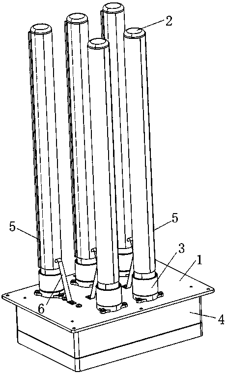
[0047] See attached figure 1 , the high-energy ion generator includes a plurality of ion tubes 2 arranged on the bottom plate 1, the ion tubes 2 are fixed through the connecting seat 3, the inside of the connecting seat 3 is connected to the conductive layer of the inner wall of the ion tube 2 through a conductive rod, and the conductive rod passes through the bottom plate 1 and the bottom plate The electric box 4 below 1 is connected to supply high voltage for the ion tube 2, and the ion tube 2 is wrapped with a conductive grid 5, and the conductive grid 5 is connected to the ground terminal of the power supply through the contact plate 6, and the high voltage is discharged in the glass medium of the ion tube 2, Alpha particles are generated to ionize the oxygen in the air into ions.

[0048] See attac...


PUM


Abstract

The invention relates to the technical field of air purification equipment and environmental protection. The invention discloses a high-energy ion generator. A first through hole is formed in the middle of the base and is corresponded to a second through hole in the bottom plate in position; at least two fixing lugs are arranged on the outer edge of the base; a kit is arranged above the base; a third through hole is formed in the bottom; the ion tube is matched with the inner wall of the kit; conductive rods are fixedly arranged in the first through hole and the third through hole; conductiveelastic sheets are arranged at the heads of the conductive rods; the conducting rod penetrates through the second through hole of the bottom plate; a connector is arranged at the tail end of the conducting rod, a first sealing groove is formed in the bottom of the base, a first sealing ring is arranged in the first sealing groove, a second sealing groove is formed in the top of the base, a secondsealing ring is arranged in the second sealing groove, the base and the bottom plate are sealed through the first sealing ring, and the sleeve piece and the base are sealed through the second sealingring. Multiple sealing is used for guaranteeing the air dryness in the ion tube, so that installation is convenient, and the service life of the ion tube is prolonged.

Description

technical field [0001] The invention relates to the technical fields of air purification equipment and environmental protection, in particular to a high-energy ion generator. Background technique [0002] The principle of the high-energy ion generator is to generate a large number of alpha particles during the electrode discharge process, and ionize the oxygen in the air into positive and negative oxygen ions. Widely used in many fields such as polluting industries, medical systems, and household air purification. [0003] The existing technology is to place electrodes inside and outside the ion tube, and discharge ionized air through the glass medium. During the glass dielectric discharge process, the inside of the ion tube should be kept dry. Water vapor and impurities will affect the life of the ion tube and cause the ion tube to burst. [0004] The existing ion tube has poor sealing performance, and is only sealed by the contact between the ion tube port and the connec...

Claims


Application Information

Patent Timeline
Patent Type & Authority Applications(China)
IPC IPC(8): B01D53/32
CPCB01D53/32
Inventor 路顺良
Owner SHANGHAI FENGJING ENVIRONMENTAL PROTECTION EQUIP CO LTD
Why Eureka
Eureka Blog
Learn More