Jaw crusher with high safety coefficient

A technology of jaw crusher and safety factor, which is applied in the field of cement manufacturing, can solve the problems of reducing safety, staff injury, debris flying out, etc., and achieve the effect of improving heat dissipation, strong practicability, and improving safety

Active Publication Date: 2020-08-18
郎溪县振达矿业有限责任公司
9 Cites 1 Cited by

AI-Extracted Technical Summary

Problems solved by technology

[0003] During the use of the existing jaw crusher, a large amount of dust will be generated, which will reduce the air quality in the working area. Not only that, but the...

Method used

Cement raw material is put into main body 1 from feed hole, and cement raw material is positioned between static jaw plate 2 and movable alligator plate 3, drives movable jaw plate 3 along perpendicular to static jaw plate 2 directions reciprocatingly by power unit move, so that the movable crocodile plate 3 can squeeze the cement raw material to crush the raw material, and then the crushed raw material is discharged from the discharge hole. Here, the function of setting the dus...

Abstract

The invention relates to a jaw crusher with the high safety coefficient. The jaw crusher with the high safety coefficient comprises a main body, a fixed jaw plate, a movable jaw plate and a power device, wherein the main body is in a cuboid shape, the fixed jaw plate, the movable jaw plate and the power device are all arranged in the main body, the fixed jaw plate is vertically arranged, the movable jaw plate is arranged on one side of the fixed jaw plate, the power device drives the movable jaw plate to reciprocate in the direction perpendicular to the fixed jaw plate, a feeding hole is formed in the top of the main body, a discharging hole is formed in the bottom of the main body, a dust collection mechanism and a protection mechanism are arranged on the main body, the dust collection mechanism comprises a water tank, a dust collection assembly and two connecting assemblies, and the connecting assemblies comprise supporting blocks, moving rods, fixing blocks, springs and through holes. According to the jaw crusher with the high safety coefficient, the dust removal function is achieved through the dust suction mechanism, and in addition, the safety is improved through the protection mechanism.

Application Domain

Dirt cleaningGrain treatments

Technology Topic

Safety coefficientEngineering +4

Image

  • Jaw crusher with high safety coefficient
  • Jaw crusher with high safety coefficient
  • Jaw crusher with high safety coefficient

Examples

  • Experimental program(1)

Example Embodiment

[0026] The present invention will now be described in further detail with reference to the drawings. These drawings are all simplified schematic diagrams, which merely illustrate the basic structure of the present invention in a schematic manner, so they only show the structures related to the present invention.
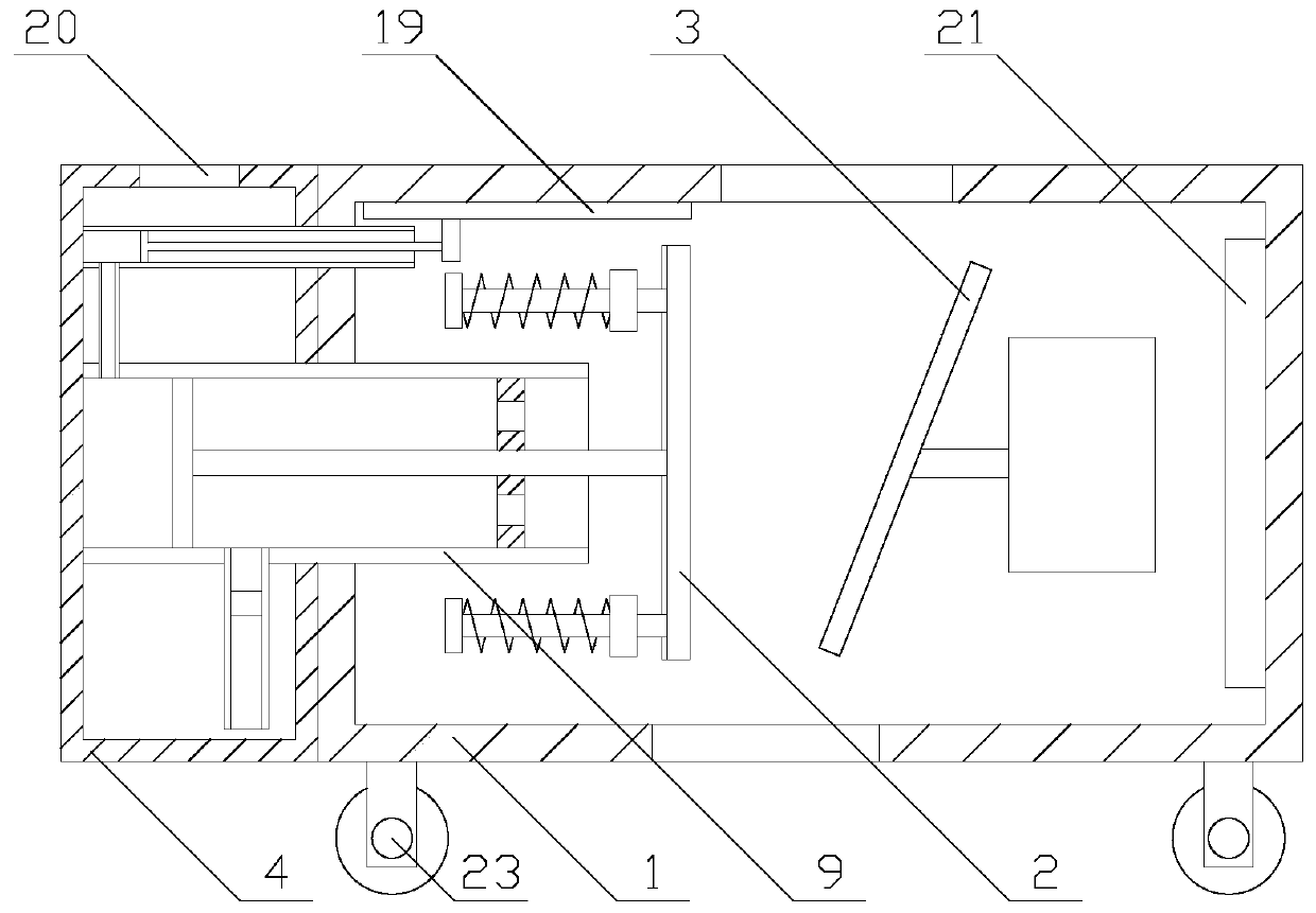
[0027] Such as figure 1 As shown, a jaw crusher with a high safety factor includes a main body 1, a static jaw plate 2, a movable jaw plate 3 and a power device. The main body 1 has a rectangular parallelepiped shape, the static jaw plate 2, the movable jaw plate 3 and the power device are both arranged in the main body 1, the static jaw 2 is arranged vertically, the movable jaw 3 is arranged on one side of the static jaw 2, and the power device drives the movable jaw 3 along the vertical to the static The jaw plate 2 moves back and forth, the top of the main body 1 is provided with a feed hole, the bottom of the main body 1 is provided with a discharge hole, and the main body 1 is provided with a dust suction mechanism and a protection mechanism;
[0028] Put the cement raw material into the main body 1 from the feed hole, and place the cement raw material between the static jaw plate 2 and the movable crocodile plate 3, and drive the movable jaw plate 3 to reciprocate along the direction perpendicular to the static jaw plate 2 through the power device. The crocodile board 3 can squeeze the cement raw materials to crush the raw materials, and the crushed raw materials are discharged from the discharge hole. Here, the function of the dust suction mechanism is to absorb the dust generated in the crushing process of the raw materials, and set up protection The function of the mechanism is to prevent the debris generated during the crushing process from flying out of the feed hole and hurting people, improving safety.
[0029] Such as Figure 2-3 As shown, the dust suction mechanism includes a water tank 4, a dust suction component, and two connecting components. The water tank 4 is fixed on the outer wall of the main body 1, and the water tank 4 is located on a side of the static jaw 2 away from the movable jaw 3. On the other hand, the water tank 4 is provided with clean water, the top of the water tank 4 is provided with an air outlet, the connecting assembly is evenly arranged on the side of the static jaw 2 away from the movable jaw 3, and the dust suction assembly is arranged at Inside the water tank 4;
[0030] The connecting assembly includes a supporting block 5, a moving rod 6, a fixed block 7, a spring 8 and a through hole. The moving rod 6 is perpendicular to the static jaw plate 2, and one end of the moving rod 6 is fixed on the static jaw plate 2. The fixed block 7 is fixed on the other end of the moving rod 6, the supporting block 5 is fixed on the inner wall of the main body 1, the through hole is provided on the supporting block 5, and the moving rod 6 passes through the through hole and communicates with The inner wall of the hole is slidingly connected, the spring 8 is located between the fixed block 7 and the support block 5, the support block 5 is connected to the fixed block 7 through the spring 8, and a gap is provided between the static jaw 2 and the support block 5 ;
[0031] The dust suction assembly includes a dust suction pipe 9, a moving plate 10, a transmission rod 11, a connecting pipe 12, a fixed ring 13, a first one-way valve 14 and two second one-way valves 15, the dust suction pipe 9 and The static jaw 2 is vertical and located on the side of the static jaw 2 away from the crocodile plate 3, the dust suction pipe 9 is located between the two moving rods 6, and the side of the main body 1 close to the water tank 4 is provided with a second A connecting hole, the side of the water tank 4 close to the main body 1 is provided with a second connecting hole, the dust suction pipe 9 passes through the first connecting hole and the second connecting hole sequentially, and the inner wall of the first connecting hole and The inner walls of the second connecting holes are all sealed and fixedly connected to the dust suction pipe 9. One end of the dust suction pipe 9 is sealed and fixedly connected to the inner wall of the water tank 4 on the side away from the second connecting hole. A gap is provided between the other end and the static jaw plate 2 and is smaller than the distance between the static jaw plate 2 and the supporting block 5. The moving plate 10, the transmission rod 11 and the fixed ring 13 are all arranged coaxially with the dust suction pipe 9. The movable disk 10 is sealed and fixedly connected to the inner wall of the dust suction pipe 9, the diameter of the transmission rod 11 is equal to the inner diameter of the fixed ring 13, and the transmission rod 11 is located between the movable disk 10 and the static jaw plate 2. The static jaw 2 is fixed on the moving plate 10 by a transmission rod 11, a gap is provided between the moving plate 10 and the inner wall of the water tank 4 on the side away from the second connecting hole, and the fixed ring 13 is arranged on the dust suction pipe 9 and located between the moving plate 10 and the static jaw 2, the fixed ring 13 is sealed and fixedly connected to the inner wall of the dust suction pipe 9, the transmission rod 11 passes through the fixed ring 13, the transmission rod 11 and the fixed ring The inner wall of 13 is slidably connected in a sealed manner. The fixing ring 13 is provided with two through holes, which are evenly distributed in the circumferential direction with the axis of the transmission rod 11 as the center. The second one-way valve 15 is connected to the through hole. One corresponding and installed in the through hole, the connecting pipe 12 is parallel to the static jaw plate 2, and one end of the connecting pipe 12 is fixed at the bottom of the dust suction pipe 9 and communicates with the dust suction pipe 9. The other end is set in clean water, the connecting pipe 12 is located between the moving plate 10 and the fixed ring 13, and the first one-way valve 14 is installed in the connecting pipe 12;
[0032] When the movable crocodile plate 3 moves in the direction close to the static jaw plate 2, the movement of the movable crocodile plate 3 pushes the static jaw plate 2 toward the support block 5 through the raw materials, and the movement of the static jaw plate 2 drives the moving rod 6 and the fixed block 7 Realize synchronous movement and stretch the spring 8. When the static jaw plate 2 and the support block 5 abut, the moving crocodile plate 3 continues to move towards the static jaw plate 2 to make the moving crocodile plate 3 to the cement material When the crocodile plate 3 moves away from the static jaw plate 2, the static jaw plate 2 is reset under the elastic action of the spring 8, and when the crocodile plate 3 and the static jaw plate 2 After the distance increases, the broken distance can be discharged from the discharge hole under the action of gravity. In this cycle, the reciprocating movement of the static jaw 2 can be realized. When the static jaw 2 moves toward the support block 5, the static jaw The movement of the plate 2 is driven by the transmission rod 11 to drive the moving plate 10 to move synchronously in the dust suction pipe 9. Through the one-way characteristics of the first one-way valve 14 and the second one-way valve 15, the air in the main body 1 is delivered to Inside the dust suction pipe 9 and move from the through hole to between the fixed ring 13 and the moving plate 10, when the static jaw 2 moves away from the support block 5, the air in the dust suction pipe 9 cannot be discharged from the through hole at this time , The air in the dust suction pipe 9 is transported from the connecting pipe 12 to the water tank 4, and the air rises in the form of bubbles in the water. Here, through the flow of air, the dust in the main body 1 can be transported to the water along with the airflow , And make the dust dissolve in the water, and the clean air will be discharged from the pores after rising in the water, realizing the function of dust removal.
[0033] Such as Figure 4 As shown, the protection mechanism is located on the side of the feed hole close to the water tank 4, the protection mechanism includes a piston 16, a trachea 17, a conduit 18 and a protective plate 19, and a side of the water tank 4 close to the main body 1 is provided The first mounting hole, the side of the main body 1 close to the water tank 4 is provided with a second mounting hole, the pipe 18 is parallel to the dust suction pipe 9, and the pipe 18 passes through the first mounting hole and the second mounting hole in turn The inner wall of the first mounting hole and the inner wall of the second mounting hole are both sealed and fixedly connected to the pipe 18, the piston 16 is matched with the pipe 18 and installed in the pipe 18, and one end of the pipe 18 is connected to the water tank 4 The inner wall on the side away from the first mounting hole is sealed and fixedly connected. The duct 18 communicates with the dust suction pipe 9 through the air pipe 17, and the connection between the air pipe 17 and the pipe 18 is located on the side of the piston 16 away from the feed hole, The connection between the air pipe 17 and the dust suction pipe 9 is located on the side of the moving plate 10 away from the transmission rod 11, the protective plate 19 is horizontally arranged in the main body 1 and is attached to the top of the main body 1, the piston 16 The protective plate 19 is fixedly connected.
[0034] When the moving plate 10 moves in the direction away from the crocodile plate 3 in the dust suction pipe 9, the air in the dust suction pipe 9 is squeezed and transported to the duct 18 through the air pipe 17, so that the air pressure in the duct 18 increases , Under the action of air pressure, the piston 16 can be moved toward the crocodile plate 3, the movement of the piston 16 drives the protective plate 19 to realize synchronous movement, and the protective plate 19 covers the feed hole, which can prevent the raw material from being crushed. The generated debris flies out of the feed hole and hurts people, which improves safety. When the movable plate 10 is reset, the air in the duct 18 is transported to the dust suction pipe 9 through the air pipe 17, and the air in the duct 18 When the air pressure is reduced, the piston 16 can drive the protective plate 19 to reset under the action of the air pressure.
[0035] Preferably, in order to reduce the gap between the moving plate 10 and the inner wall of the dust suction pipe 9, the connection between the moving plate 10 and the dust suction pipe 9 is coated with sealing grease.
[0036] The function of the sealing grease is to reduce the gap between the movable plate 10 and the inner wall of the dust suction pipe 9 and improve the sealing performance.
[0037] Preferably, in order to reduce the friction between the moving rod 6 and the inner wall of the through hole, the moving rod 6 is coated with lubricating oil.
[0038] The function of the lubricating oil is to reduce the friction between the movable rod 6 and the inner wall of the through hole, and improve the smoothness of the movement of the movable rod 6.
[0039] Preferably, in order to facilitate the installation of the movable rod 6, both ends of the movable rod 6 are provided with chamfers.
[0040] The function of the chamfer is to reduce the diameter of the movable rod 6 when it passes through the through hole, which has the effect of facilitating installation.
[0041] Preferably, in order to improve the dust removal effect, a filter 20 is installed in the air hole.
[0042] The function of the filter screen 20 is to prevent dust from not being completely dissolved in the water and being discharged from the pores with air. The filter screen 20 can realize the retention of dust and improve the dust removal effect.
[0043] Preferably, in order to prolong the service life of the water tank 4, the water tank 4 is provided with an anticorrosive galvanized layer.
[0044] The function of the anticorrosive galvanized layer is to enhance the anti-rust ability of the water tank 4 and prolong the service life of the water tank 4.
[0045] Preferably, in order to reduce noise, an acoustic panel 21 is provided in the main body 1.
[0046] The function of the sound absorbing panel 21 is to absorb the noise in the main body 1 to achieve noise reduction.
[0047] Preferably, in order to prevent the cement material from slipping, the side of the static jaw plate 2 close to the alligator plate 3 is provided with anti-slip patterns.
[0048] The function of the anti-skid pattern is to improve the friction between the cement raw material and the static jaw plate 2, and prevent slippage and affect the reliability of crushing.
[0049] Preferably, in order to achieve buffering and vibration reduction, a rubber block 22 is laid on the side of the static jaw plate 2 close to the support block 5.
[0050] The rubber block 22 has the characteristic of relatively soft texture, which can reduce the impact force generated when the static jaw 2 abuts the support block 5, and realizes buffering and damping.
[0051] Preferably, in order to facilitate the transportation of the device, a roller 23 is provided at the bottom of the main body 1.
[0052] The function of the roller 23 is to facilitate the transportation of the equipment and improve the convenience.
[0053] Put the cement raw material into the main body 1 from the feed hole, and place the cement raw material between the static jaw plate 2 and the movable crocodile plate 3. The movable jaw plate 3 is driven to reciprocate along the direction perpendicular to the static jaw plate 2 through the power device. When the movable crocodile plate 3 moves in the direction close to the static jaw plate 2, the movement of the movable crocodile plate 3 is realized by the raw material pushing the static jaw plate 2 toward the support block 5, and the movement of the static jaw plate 2 drives the moving rod 6 and the fixed block 7. Move synchronously and stretch the spring 8. When the static jaw 2 abuts the support block 5, the moving crocodile plate 3 continues to move toward the static jaw 2 to make the moving crocodile plate 3 perform the cement Squeeze to crush the raw materials, and the crushed raw materials are discharged from the discharge hole, and as the moving plate 10 moves away from the alligator plate 3 in the dust suction pipe 9, the air in the dust suction pipe 9 is squeezed The pressure is delivered to the catheter 18 through the trachea 17, so that the air pressure in the catheter 18 increases. Under the action of the air pressure, the piston 16 can move toward the alligator plate 3, and the movement of the piston 16 drives the protective plate 19 to realize synchronous movement. , And make the protective plate 19 cover the feed hole, which can prevent the debris generated during the crushing process from flying out of the feed hole and hurt people, which improves safety;
[0054] When the movable crocodile plate 3 moves away from the static jaw plate 2, the static jaw plate 2 is reset under the elastic action of the spring 8, and when the distance between the movable crocodile plate 3 and the static jaw plate 2 increases, the broken It can be discharged from the discharging hole under the action of gravity. This cycle can realize the reciprocating movement of the static jaw 2. When the static jaw 2 moves toward the support block 5, the movement of the static jaw 2 passes through the transmission rod 11. The moving plate 10 is driven to move synchronously in the dust suction pipe 9. Through the one-way characteristics of the first one-way valve 14 and the second one-way valve 15, the air in the main body 1 is transported to the dust suction pipe 9, and from The through hole moves between the fixed ring 13 and the moving plate 10. When the static jaw plate 2 moves away from the support block 5, the air in the dust suction pipe 9 cannot be discharged from the through hole at this time, so that the dust inside the suction pipe 9 The air is transported from the connecting pipe 12 to the water tank 4, and the air rises in the form of bubbles in the water. Here, through the flow of air, the dust in the main body 1 can be transported to the water along with the airflow, and the dust is dissolved in the water. The clean air rises in the water and is then discharged from the air holes to achieve the function of dust removal. Moreover, by moving the moving plate 10 toward the direction of the alligator plate 3, the air in the duct 18 is transported to the dust collection through the air pipe 17 In the pipe 9 and the air pressure in the conduit 18 is reduced, the piston 16 can drive the protective plate 19 to reset under the action of the air pressure, so that the cement material can be put into the main body 1 again from the feed hole.
[0055] Compared with the prior art, the jaw crusher with high safety factor realizes the function of dust removal through the dust collection mechanism. Compared with the existing dust collection mechanism, the dust collection mechanism can realize the directional flow of air in the main body 1. That is to say, the heat in the main body 1 can be discharged with the air, and the heat dissipation effect of the main body 1 is improved. Not only that, but also the safety is improved by the protection mechanism. Compared with the existing protection mechanism, the protection mechanism and the dust removal mechanism achieve The integrated linkage structure is more practical.
[0056] Taking the above-mentioned ideal embodiment according to the present invention as enlightenment, through the above-mentioned description content, relevant staff can make various changes and modifications without departing from the scope of the technical idea of ​​the present invention. The technical scope of the present invention is not limited to the content of the description, and its technical scope must be determined according to the scope of the claims.

PUM

no PUM

Description & Claims & Application Information

We can also present the details of the Description, Claims and Application information to help users get a comprehensive understanding of the technical details of the patent, such as background art, summary of invention, brief description of drawings, description of embodiments, and other original content. On the other hand, users can also determine the specific scope of protection of the technology through the list of claims; as well as understand the changes in the life cycle of the technology with the presentation of the patent timeline. Login to view more.

Similar technology patents

Welding and radiating turntable

Owner:WUXI UNITE ENERGY TECH CO LTD

Blast furnace cooling tuyere

Owner:常州市武进长虹结晶器有限公司 +1

Classification and recommendation of technical efficacy words

  • Improve cooling effect
  • improve security

Backlight unit

InactiveCN103336388AImprove cooling effecteven heat distribution
Owner:TCL CHINA STAR OPTOELECTRONICS TECH CO LTD

Novel air film hole with improved cooling efficiency

InactiveCN103452595AImprove cooling effectWide air-conditioning coverage
Owner:QINGDAO UNIV OF SCI & TECH

Water-cooled engine and cylinder cover thereof

ActiveCN103867332ATake away heat loadImprove cooling effect
Owner:ANHUI HUALING AUTOMOBILE

Pesticide micro-capsule granules and preparation method thereof

InactiveCN102100229Alow toxicityimprove security
Owner:联合国南通农药剂型开发中心 +1

Method for achieving user authentication by utilizing camera

InactiveCN103678984Aimprove securityGuaranteed picture quality
Owner:湖北微模式科技发展有限公司
Why Eureka
Try Eureka