Disinfection supply center instrument cleaning device
A technology for cleaning devices and supply centers, which is applied in the field of instrument cleaning and can solve problems such as incomplete cleaning
- Summary
- Abstract
- Description
- Claims
- Application Information
AI Technical Summary
Problems solved by technology
Method used
Image

Examples
Embodiment 1
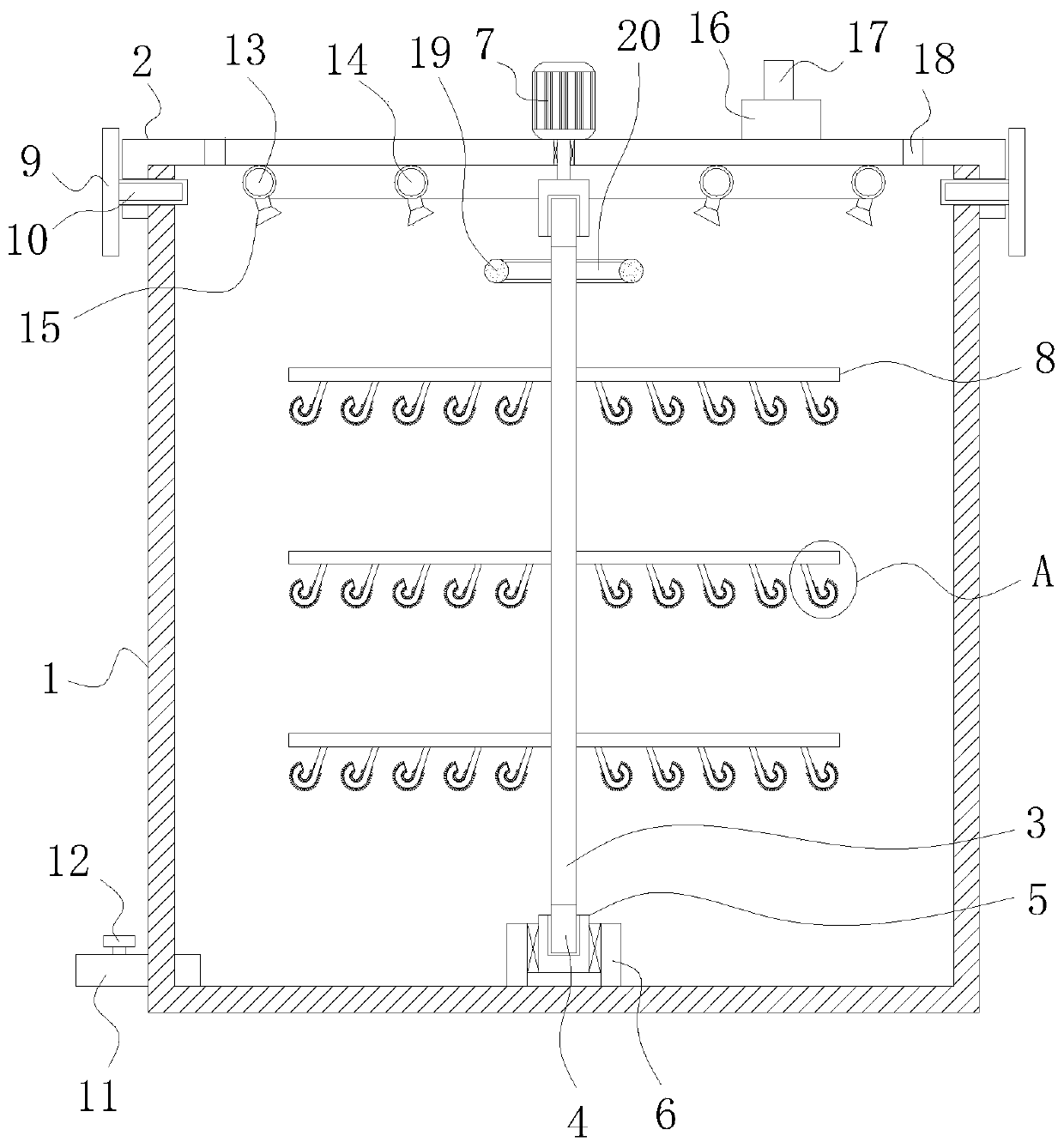
[0022] refer to Figure 1-5 , an apparatus cleaning device for a disinfection supply center, comprising a box body 1, on which a box cover 2 with an inverted "匚"-shaped longitudinal section is engaged, and position limiting mechanisms are provided on both sides of the box cover 2, and the box body 1. There is a rotating rod 3 vertically inside. The upper and lower ends of the rotating rod 3 are vertically welded with a limit rod 4 with a cross section in the shape of a "ten". The limit rod 4 is provided with a limit block 5. There is an insertion slot corresponding to the limit rod 4, and the limit rod 4 is inserted in the insertion slot. One of the limit blocks 5 is fitted with a fixed cylinder 6 through a bearing rotation, and the bottom end of the fixed cylinder 6 Vertically welded on the inner bottom wall of the box body 1, a motor 7 is welded at the center of the upper surface of the box cover 2, the top of the output shaft of the motor 7 penetrates the box cover 2 and ex...
Embodiment 2
[0026] refer to figure 1 and 5 , as another preferred embodiment of the present invention, the difference from Embodiment 1 is that the position limiting mechanism includes two insertion rods 10, and the two insertion rods 10 vertically penetrate through the two ends of one side of the box cover 2 respectively. The side of the body 1 is provided with an insertion hole corresponding to the insertion rod 10, one end of the insertion rod 10 is installed in the insertion hole, and the other end of the insertion rod 10 is vertically fixed with a pull rod 9, and the insertion rod 10 is vertically fixed. Comprising an iron rod and an anti-slip rubber sleeve, one end of the iron rod is vertically welded on the pull rod 9, the anti-slip rubber sleeve is fixedly set on the iron rod, and the anti-slip rubber sleeve is in contact with the insertion hole. The iron rod is to ensure the hardness of the insertion rod 10, and the anti-slip rubber sleeve is to improve the friction force of the...
Embodiment 3
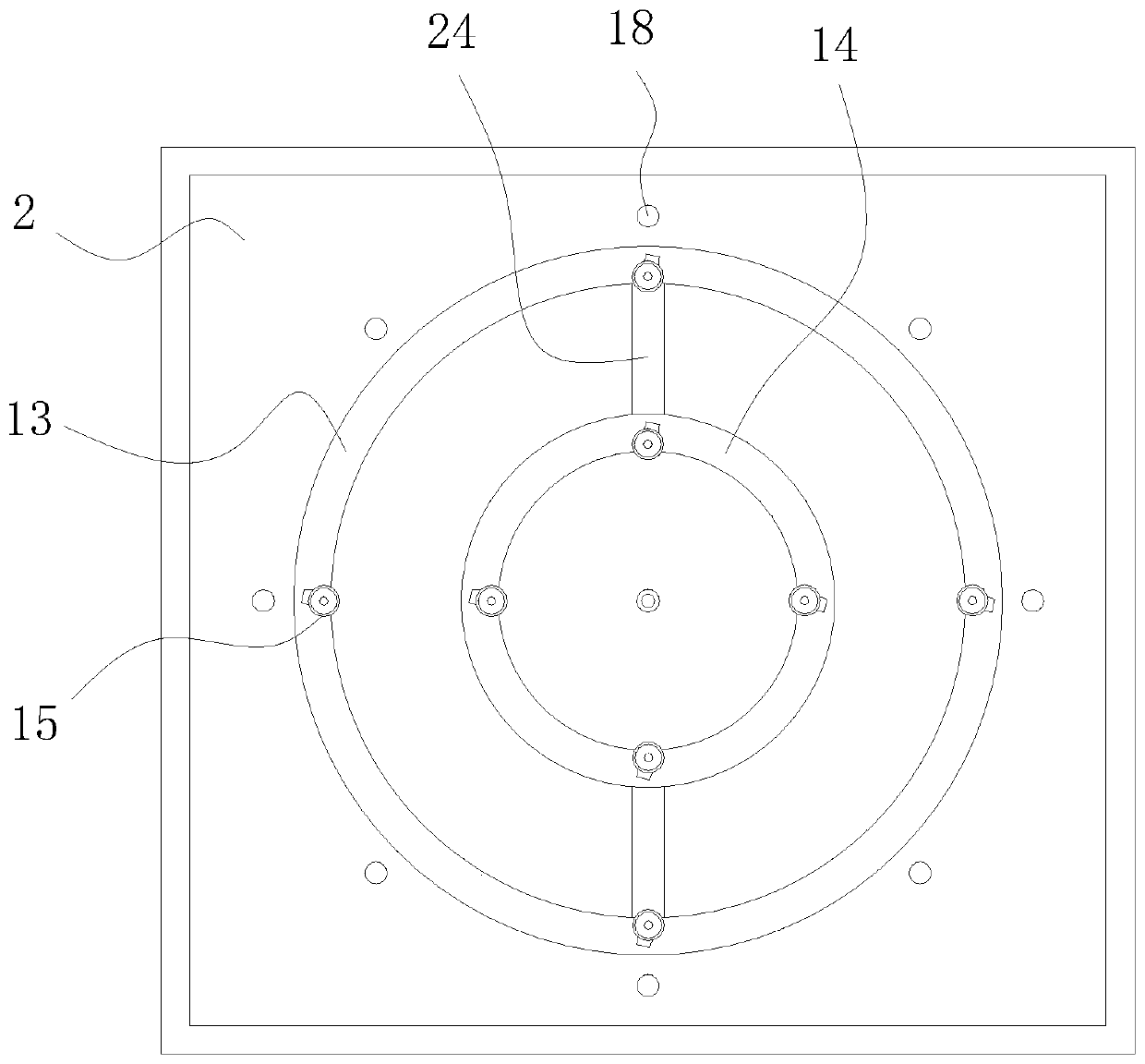
[0028] refer to figure 1 , as another preferred embodiment of the present invention, the difference from Embodiment 1 is that holes 18 are equidistant and run through the case cover 2, and a plurality of holes 18 are arranged in a circle on the case cover 2 with the motor 7 as the center , the connecting rod 20 is welded equidistantly on one side of the top of the rotating rod 3, and a plurality of connecting rods 20 are arranged in a circle with the rotating rod 3 as the center of a circle. Ring 19 set. Under the effect of the hole 18, the stability of the air pressure in the box body 1 can be guaranteed, so that the instrument cleaning device of the disinfection supply center can work more safely and efficiently. By pulling the ring 19, the position of the rotating rod 3 can be moved conveniently.
PUM
 Abstract
Description
Claims
Application Information
 - R&D
- Intellectual Property
- Life Sciences
- Materials
- Tech Scout
- Unparalleled Data Quality
- Higher Quality Content
- 60% Fewer Hallucinations
Browse by: Latest US Patents, China's latest patents, Technical Efficacy Thesaurus, Application Domain, Technology Topic, Popular Technical Reports.
© 2025 PatSnap. All rights reserved.Legal|Privacy policy|Modern Slavery Act Transparency Statement|Sitemap|About US| Contact US: help@patsnap.com