Automobile anti-collision beam structure based on bionic design

A technology of anti-collision beams and automobiles, which is applied in the direction of substructure, vehicle parts, transportation and packaging, etc. It can solve the problems of unfavorable space layout and lightweight design, the weight of anti-collision beams, large volume, and unfavorable vehicle safety performance, etc., to achieve Reduce the layout of connections and spaces, simplify the installation process, and improve the impact resistance effect

Inactive Publication Date: 2020-08-18
丹阳市车船装饰件有限公司
View PDF5 Cites 0 Cited by
  • Summary
  • Abstract
  • Description
  • Claims
  • Application Information

AI Technical Summary

Problems solved by technology

[0005] For this reason, the embodiment of the present invention provides an automobile anti-collision beam structure based on bionic design. The energy-absorbing sleeve and the energy-absorbing base are embedded in each other to realize that the anti-collision beam itself has a high-strength structure and a rapid The effect of decomposing collision energy absorption is transmitted, and the installation process is simplified, the connection between parts and the arrangement of space are reduced, the complexity of assembly is reduced, and the lightweight design of the anti-collision beam is realized to solve the anti-collision of automobiles in the prior art The weight and volume of the beam assembly are relatively large, which is not conducive to the space layout and lightweight design of the vehicle. If the parts are thinned, the strength of the anti-collision beam will be reduced, which is not conducive to the safety performance of the vehicle.

Method used


Image

  • Automobile anti-collision beam structure based on bionic design
  • Automobile anti-collision beam structure based on bionic design
  • Automobile anti-collision beam structure based on bionic design

Examples


Embodiment Construction

[0029] The embodiments of the present invention are described below by specific specific embodiments. Those who are familiar with the technology can easily understand other advantages and effects of the present invention from the contents disclosed in this specification. Obviously, the described embodiments are part of the present invention. , not all examples. Based on the embodiments of the present invention, all other embodiments obtained by those of ordinary skill in the art without creative efforts shall fall within the protection scope of the present invention.

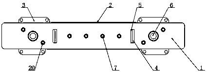
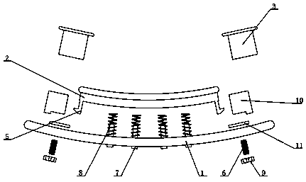
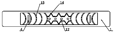
[0030] Refer to the manual attached Figure 1-7 , An automobile anti-collision beam structure based on a bionic design of this embodiment includes a cross beam main body 1, the shape of the cross beam main body 1 is an arc, and the interior of the cross beam main body 1 is provided with a second cell-shaped groove 15 along the length direction, so One side of the beam main body 1 is fixedly installed with energ...


PUM


Abstract

The invention discloses an automobile anti-collision beam structure based on bionic design, and particularly relates to the field of automobile anti-collision beams. The automobile anti-collision beamstructure comprises a cross beam body, the cross beam body is in an arc shape, a second cell-shaped groove is formed in the cross beam body in the length direction, energy absorption boxes are fixedly installed at the two ends of one side of the cross beam body in the transverse direction respectively, and a reinforcing assembly is fixedly installed on the portion, between the two energy absorption boxes, of the cross beam body. The energy absorption box comprises screws inserted into the two transverse ends of the cross beam body, energy absorption sleeve bases are fixedly installed at the ends, close to the reinforcing assemblies, of the screws, the ends, close to the energy absorption sleeve bases, of the outer surfaces of the screws are sleeved with reinforcing pieces, and nuts are fixedly arranged at the ends of one ends of the screws. The anti-collision beam has a high-strength structure and also has the effect of rapidly transmitting, decomposing and absorbing collision energy,the installation process is simplified, connection between parts and arrangement of space are reduced, the assembly complexity is reduced, and the lightweight design of the anti-collision beam is achieved.

Description

technical field [0001] Embodiments of the present invention relate to the field of automobile anti-collision beams, in particular to an automobile anti-collision beam structure based on bionic design. Background technique [0002] Safety, energy saving and environmental protection are the eternal themes of automobile development, and automobile safety is the top priority of the three major themes. Development brings adverse effects, and the operational safety of automobiles is increasingly concerned. [0003] When a collision accident occurs, the safety of the occupants in the vehicle is mainly protected by the body structure. In a frontal low-speed collision, the bumper is mainly used to protect the car body. The anti-collision beam is a very important safety part in the car body, and it is the first safety barrier when the car collides. It is mainly composed of a beam, an energy-absorbing box and a mounting plate. Bending and deforming under the impact force, then the e...

Claims


Application Information

Patent Timeline
IPC IPC(8): B62D21/15
CPCB62D21/15
Inventor 李德兴曾庆国龚志辉
Owner 丹阳市车船装饰件有限公司
Why Eureka
Try Eureka