Automatic mushroom liquid strain injection machine

A liquid strain, automatic injection technology, applied in the field of injection machines, can solve problems such as low injection efficiency

Pending Publication Date: 2020-08-18
王炳辉
View PDF1 Cites 4 Cited by
  • Summary
  • Abstract
  • Description
  • Claims
  • Application Information

AI Technical Summary

Problems solved by technology

[0005] In order to overcome the shortcomings of manual repeated operations and low injection efficiency in the process of manually injecting mushroom liquid strains, and the need for manual replacement of test tubes, the technical problem of the present invention is to provide a method that can automatically inject mushroom liquid strains into test tubes, automatically Replace the test tube, reduce the manual operation of the mushroom liquid strain automatic injection machine

Method used


Image

  • Automatic mushroom liquid strain injection machine
  • Automatic mushroom liquid strain injection machine
  • Automatic mushroom liquid strain injection machine

Examples


Embodiment 1

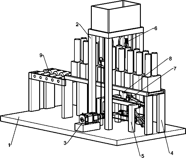
[0041] A kind of automatic injection machine for mushroom liquid spawn, such as figure 1 As shown, it includes a base 1, a first support 2, a motor 3, a second support 4, a third support 5, an infusion mechanism 6 and an intermittent feeding mechanism 7, the middle part of the right side of the base 1 is provided with the first support 2, and the base 1 A motor 3 is installed on the front side of the right, and the motor 3 is located directly in front of the first support 2. A second support 4 is arranged between the left and right sides of the base 1. The second support 4 is located below the first support 2. The right side of the base 1 is equipped with a The third support 5, the third support 5 is located below the second support 4, the output shaft of the first support 2 and the motor 3 is provided with an infusion mechanism 6, the parts of the infusion mechanism 6 and the third support 5 and the second support 4 Intermittent feeding mechanism 7 is installed between.

[0...

Embodiment 2

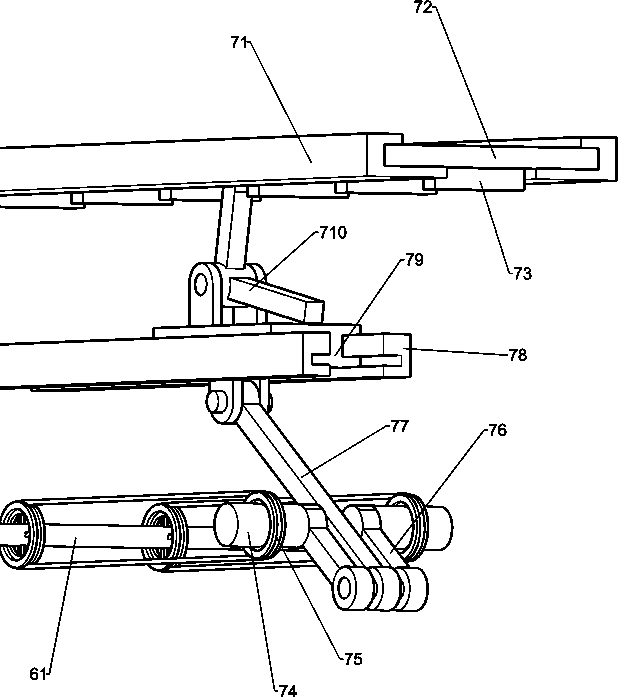
[0044] In particular, refer to Figure 1-4As shown, the infusion mechanism 6 includes an output shaft 61, a first shaft 62, a first belt assembly 63, a cam 64, a liquid bacteria storage box 65, a cylindrical sliding sleeve 66, a liquid injection pipe 67, a moving water pipe 68, and a first spring 611 With the first roller 612, the output shaft 61 is installed on the output shaft of the motor 3, and the first shaft 62 is provided with the first shaft 62 in the front and rear sides of the first support 2 top. The first belt assembly 63 is connected between the two parts, the inboard of the first rotating shaft 62 is equipped with a cam 64, the top of the first support 2 is provided with a liquid spawn storage box 65, and the front and rear sides of the liquid spawn storage box 65 bottom are A cylindrical sliding sleeve 66 is provided, and a moving water pipe 68 is slidingly installed in the cylindrical sliding sleeve 66. The inner side of the lower part of the moving water pipe ...

Embodiment 3

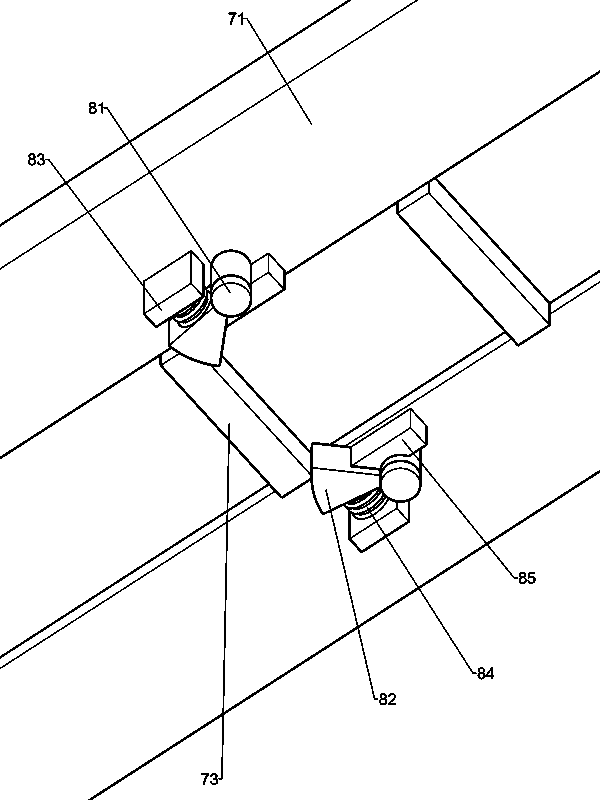
[0049] according to figure 1 with Figure 5-6 As shown, a fixing mechanism 8 is also included. The fixing mechanism 8 includes a support shaft 81, a fixing block 82, a mounting plate 83, a second spring 84 and a baffle plate 85, and the right side of the bottom of the first slide rail 71 on both sides is provided with a support Shaft 81, the bottom of the first slide rail 71 between the support shafts 81 on both sides is provided with a baffle plate 85, the bottom of the first slide rail 71 on the left side of the support shaft 81 is connected with a mounting plate 83, and the mounting plates 83 on both sides are close to each other Second spring 84 is installed on the side of each side, on the support shaft 81, the fixed block 82 is connected in rotation, the end of the second spring 84 is connected with the fixed block 82, and the fixed block 82 cooperates with the block 73.


PUM


Abstract

The invention relates to an injection machine, in particular to an automatic mushroom liquid strain injection machine. Therefore, the technical problem of the invention is to provide the automatic mushroom liquid strain injection machine which can automatically inject mushroom liquid strains into a test tube, automatically replace the test tube and reduce manual operation. According to the technical scheme, the automatic mushroom liquid strain injection machine comprises a base, a first support is installed on the side portion of the base, a motor is arranged on the side portion of the base, and the motor is located right in front of the first support; the second support is installed between the left side and the right side of the base, and the second support is located below the first support. By means of the liquid conveying mechanism, strains can automatically flow into the test tubes, when a certain number of strains are contained in the test tubes under the liquid injection waterpipe, the strains in the liquid strain storage box can automatically stop flowing out, and through the fixing mechanism, when the sliding block moves rightwards, the position of the material conveyingplate can be fixed, and the sliding block is prevented from driving the material conveying plate to move rightwards.

Description

technical field [0001] The invention relates to an injection machine, in particular to an automatic injection machine for mushroom liquid strains. Background technique [0002] On the premise of shortening the growth time of mushrooms, in order to increase the yield of mushrooms at the same time, mushroom producers usually choose liquid cultivation. This liquid cultivation method requires workers to pour the liquid bacteria of mushrooms into the charging pot. Insert a straw into the feeding basin, hold the test tube in hand, put the end of the straw inside, and then press the straw, the mushroom strains in the charging basin then flow into the test tube through the straw, and the worker stops pressing the straw after the liquid strain is filled in the test tube , and replace the empty test tube to inject the mushroom liquid spawn. [0003] Patent CN209142436U discloses a liquid filling machine with good sealing performance, which includes filling machine body, support colum...

Claims


Application Information

Patent Timeline
Patent Type & Authority Applications(China)
IPC IPC(8): C12M1/00C12M1/24
CPCC12M23/08C12M23/48C12M29/26
Inventor 王炳辉
Owner 王炳辉
Why Eureka
Try Eureka