Check patentability & draft patents in minutes with Patsnap Eureka AI!

Novel fabricated box culvert and construction method thereof

A construction method and prefabricated technology, which is applied in the direction of infrastructure engineering, buildings, road bottoms, etc., can solve the problems of many connection parts, a large number of box culverts, and difficult construction, so as to facilitate waterproofing, ensure connection quality, and improve The effect of construction efficiency

Inactive Publication Date: 2020-08-18
CHANG HONG
View PDF5 Cites 4 Cited by
  • Summary
  • Abstract
  • Description
  • Claims
  • Application Information

AI Technical Summary

Problems solved by technology

The cast-in-place box culvert has attracted the attention of the industry due to its low efficiency and high construction difficulty.
[0003] At present, the prefabricated box culvert mainly adopts the form of whole section, which is pre-cast as a section of box culvert; for larger box culverts, in order to meet the hoisting requirements, it is necessary to reduce the length of each section of box culvert, resulting in a large number of box culverts , there are many connection parts, the probability of leakage is high

Method used


Image

  • Novel fabricated box culvert and construction method thereof
  • Novel fabricated box culvert and construction method thereof
  • Novel fabricated box culvert and construction method thereof

Examples


Embodiment 1

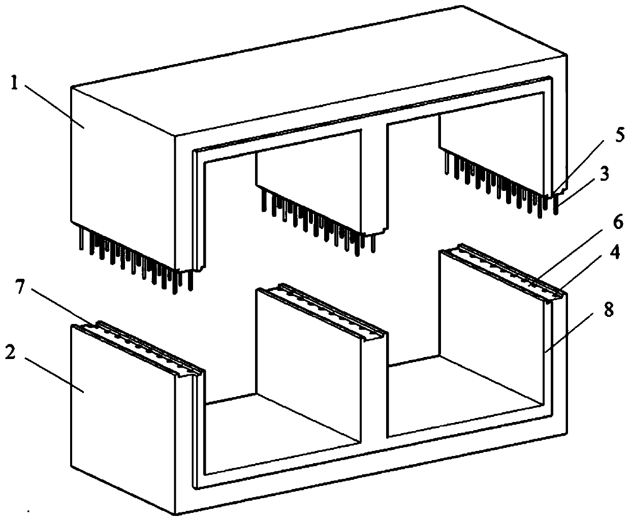
[0032] see figure 1 , a new type of assembled box culvert, mainly composed of an upper box culvert 1 and a lower box culvert 2, the upper box culvert 1 is provided with a plurality of vertical steel bars 3, and the vertical steel bars 3 protrude in the vertical direction Outside the upper box culvert 1; inside the lower box culvert 2 are provided a plurality of steel sleeves 4 adapted to the vertical steel bars in the upper box culvert.

Embodiment 2

[0034] see Figure 2-3 , a new type of assembled box culvert, mainly composed of an upper box culvert 1 and a lower box culvert 2, the upper box culvert 1 is provided with a plurality of vertical steel bars 3, and the vertical steel bars 3 protrude in the vertical direction Outside the upper box culvert 1; inside the lower box culvert 2 are provided a plurality of steel sleeves 4 adapted to the vertical steel bars in the upper box culvert.

[0035] Wherein, each section of the box culvert is provided with a longitudinal notch 7 along one end of the vertical direction, and the opposite end is provided with a longitudinal convex notch 8, and the longitudinal notch 7 and the longitudinal convex notch 8 are adapted to each other; The protrusion 8 fits with the longitudinal notch (7) and forms a cavity 9; waterproof materials can be poured into the cavity 9 or waterproof adhesive strips are set.

[0036] The bottom of the upper box culvert 1 is horizontally provided with a transve...

Embodiment 3

[0038] see figure 1 , a new type of assembled box culvert, mainly composed of an upper box culvert 1 and a lower box culvert 2, the upper box culvert 1 is provided with a plurality of vertical steel bars 3, and the vertical steel bars 3 protrude in the vertical direction The upper box culvert 1 is outside; the lower box culvert 2 is provided with a plurality of steel sleeves 4 adapted to the vertical steel bars in the upper box culvert; the vertical steel bars 3 are screwed to the steel sleeves 4 .


PUM


Abstract

The invention discloses a novel fabricated box culvert and a construction method thereof. The box culvert is mainly composed of an upper box culvert body (1) and a lower box culvert body (2), a plurality of vertical steel bars (3) are arranged in the upper box culvert body (1), and the vertical steel bars (3) extend out of the upper box culvert body (1) in the vertical direction; and a plurality of steel sleeves (4) matched with the vertical steel bars in the upper-layer box culvert are arranged in the lower-layer box culvert (2). Each section of box culvert is divided into the upper layer andthe lower layer, the layers are connected in a sleeve grouting mode, the sleeve grouting technology is different from the prior art, the sleeve is arranged at the top end of the lower component, grouting can be directly performed without special equipment, the connection compactness is guaranteed, and leakage is prevented.

Description

technical field [0001] The invention specifically relates to a novel assembled box culvert and a construction method thereof, belonging to the technical field of assembled buildings. Background technique [0002] Box culverts refer to culverts built with reinforced concrete box-shaped pipe joints; box culverts are generally constructed by cast-in-place, the bottom layer is set in the excavated trench, a layer of concrete cushion is poured, and then the processed steel bars are placed Binding on site, supporting the inner and outer molds, for larger box culverts, the lower half of the bottom plate and side walls are generally poured first, then the upper part of the side walls and the roof reinforcement are bound, the inner and outer molds are supported, and the upper half of the side walls and roof are poured; After the concrete reaches the strength required by the design, the formwork is removed, and the soil is backfilled on both sides of the box culvert at the same time. ...

Claims


Application Information

Patent Timeline
IPC IPC(8): E01F5/00E02D15/02
CPCE01F5/005E02D15/02
Inventor 常虹孔伟任宇向小芳
Owner CHANG HONG
Features
  • R&D
  • Intellectual Property
  • Life Sciences
  • Materials
  • Tech Scout
  • Unparalleled Data Quality
  • Higher Quality Content
  • 60% Fewer Hallucinations
Learn More