Shunting type drainage intercepting well

A technology of intercepting wells and diverting flow, applied in drainage structures, waterway systems, water supply devices, etc., can solve problems such as damage, affecting the treatment effect of sewage treatment plants, and changes in influent water quality.

Pending Publication Date: 2020-08-18
WUHAN MUNICIPAL ENG DESIGN & RES INST
View PDF0 Cites 2 Cited by
  • Summary
  • Abstract
  • Description
  • Claims
  • Application Information

AI Technical Summary

Problems solved by technology

[0003] Traditional interception wells include trough interception wells, weir interception wells, etc. These interception wells often have the following problems: (1) The sewage in sunny days and the mixed sewage of rain and sewage in the early stage of rainfall are not effectively diverted, but are intercepted through the same set of interception pipes Then it is discharged into the downstream water body, and the research shows that the rainwater at the beginning of the rainfall will carry a large amount of pollutants including dust in the air, ground muck and oil, etc., and the pollutants contained in it are even more than the sewage in sunny days. If it is directly transported to the sewage treatment plant, it will have a great impact or even damage the treatment system; (2) Because the traditional interception well needs to lower the elevation of the interception pipe, when the water level of the downstream water body rises, backflow will occur in the interception well, and the backflow water will It flows into the interception pipe in the interception well and into the sewage treatment plant, which will increase the treatment load of the sewage treatment plant, change the influent water quality, and affect the treatment effect of the sewage treatment plant

Method used


Image

  • Shunting type drainage intercepting well
  • Shunting type drainage intercepting well
  • Shunting type drainage intercepting well

Examples


Embodiment Construction

[0038] The principles and features of the present invention are described below in conjunction with the accompanying drawings, and the examples given are only used to explain the present invention, and are not intended to limit the scope of the present invention.

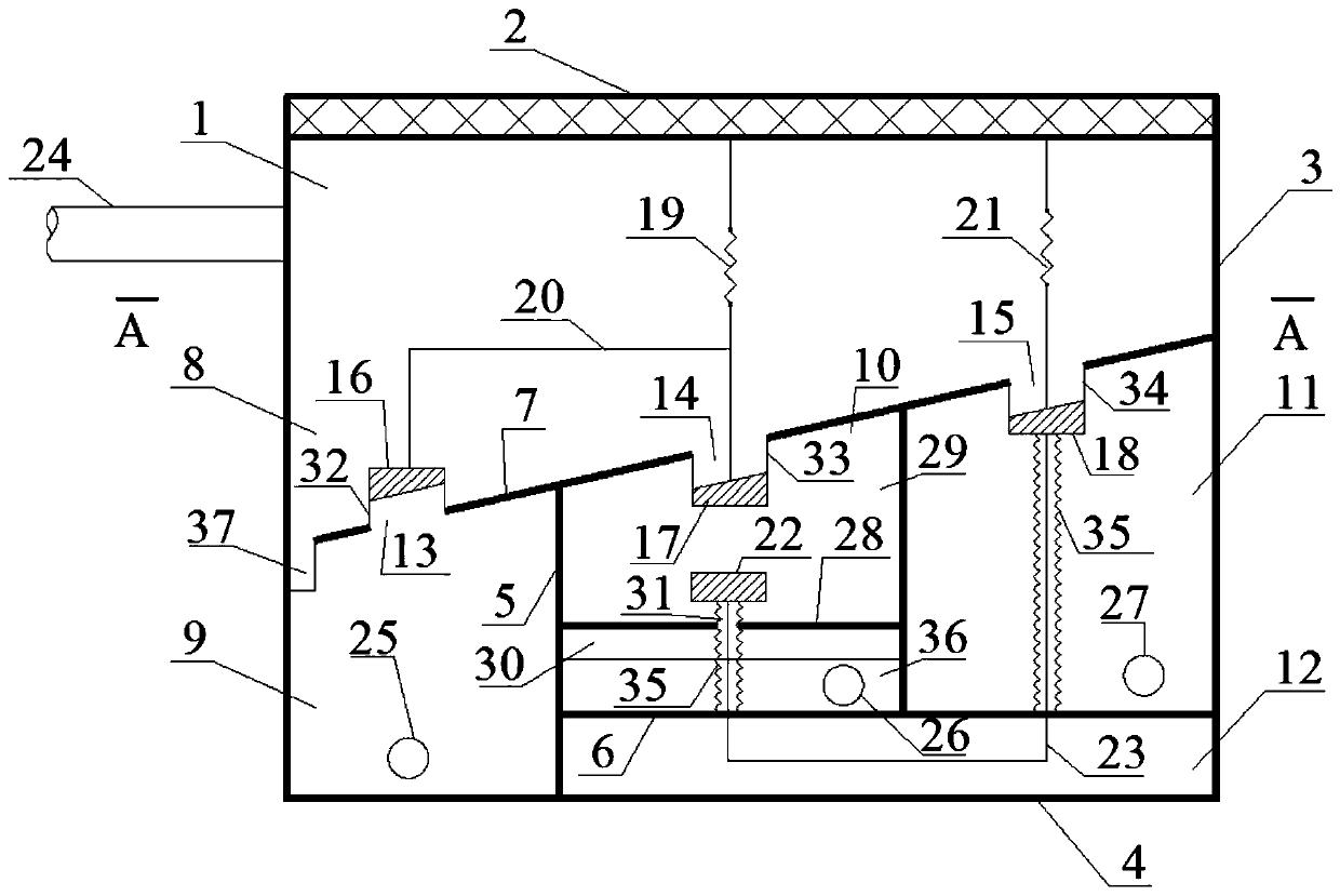
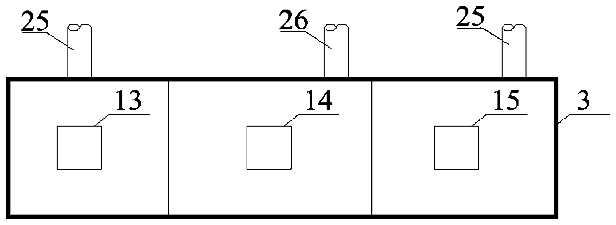
[0039] Such as figure 1 and figure 2 As shown, a diversion-type drainage interception well includes a well cavity 1 with an open upper end and a well cover 2 that is arranged at the upper end of the well cavity 1 and can open or close its upper port; the well cavity 1 is separated by a partition The water inlet chamber 8, the sewage chamber 9, the initial rain chamber 10 and the overflow chamber 11, the water inlet chamber 8 is located on the upper part of the well cavity 1, and the bottom wall of the water inlet chamber 8 is inclined, the The sewage chamber 9, the initial rain chamber 10 and the overflow chamber 11 are adjacently arranged in the lower part of the well cavity 1 in sequence, and the sewage chamber ...


PUM


Abstract

The invention relates to a shunting type drainage intercepting well. The shunting type drainage intercepting well comprises a well cavity and a well cover; and the well cavity is internally divided into a water inlet chamber, a sewage chamber, a primary rain chamber and an overflow chamber, the water inlet chamber is located at the upper part of the well cavity, the bottom wall of the water inletchamber is obliquely arranged, the sewage chamber, the primary rain chamber and the overflow chamber are sequentially and adjacently arranged at the lower part of the well cavity, the sewage chamber,the primary rain chamber and the overflow chamber all communicate with the water inlet chamber, a first linkage mechanism and a second linkage mechanism are arranged in the water inlet chamber, a water inlet pipe is arranged on the side wall of the water inlet chamber, and the lower parts of the side walls of the sewage chamber, the primary rain chamber and the overflow chamber are respectively and correspondingly provided with a sewage water outlet pipe, a primary rain water outlet pipe and an overflow water outlet pipe. According to the shunting type drainage intercepting well, sewage in sunny days and rainy sewage mixed sewage in rainy days are automatically classified and cut off, so that the subsequent sewage and primary rainy treatment facilities can be subjected to targeted treatment, water of a downstream pipeline or a water body is not prone to forming backflow in the intercepting well, so that the treatment load of the subsequent treatment facilities is reduced, and the treatment efficiency is improved.

Description

technical field [0001] The invention relates to the technical field of municipal pipelines, in particular to a diversion type drainage interception well. Background technique [0002] In the traditional urban drainage pipe network system, the interception combined drainage pipe network system is a relatively common one, which is to set up an intercepting pipe at the main drainage pipe at the end of the traditional combined drainage system that discharges into the water body. An interception well is set at the intersection of the pipe and the interception pipe. In the interception well, the sewage and the rain-sewage mixed sewage at the beginning of the rainfall are intercepted by the same set of interception pipes and sent to the sewage plant for treatment. When the water volume exceeds the drainage capacity of the interception pipe, the excess rain and sewage mixed sewage will overflow in the interception well, and the overflowed rain and sewage mixed sewage will be dischar...

Claims


Application Information

Patent Timeline
Patent Type & Authority Applications(China)
IPC IPC(8): E03F5/10
CPCE03F5/10E03F5/107E03F2201/10
Inventor 李尔曾祥英
Owner WUHAN MUNICIPAL ENG DESIGN & RES INST
Why Eureka
Try Eureka