Building supporting robot

A robot and construction technology, applied in the direction of construction, building structure, and on-site preparation of building components, can solve the problems of high labor intensity, long erection time, low production efficiency, etc., and achieve the goal of improving construction efficiency and automatic construction Effect

Pending Publication Date: 2020-08-18
正如(广东)机器人科技有限公司
View PDF0 Cites 4 Cited by
  • Summary
  • Abstract
  • Description
  • Claims
  • Application Information

AI Technical Summary

Problems solved by technology

Therefore, in the traditional construction method, a large number of workers are required to erect formwor

Method used


Image

  • Building supporting robot
  • Building supporting robot

Examples


Embodiment Construction

[0019] In order to describe the technical content, structural features, and achieved effects of the present invention in detail, the following will be described in detail in conjunction with the embodiments and accompanying drawings.

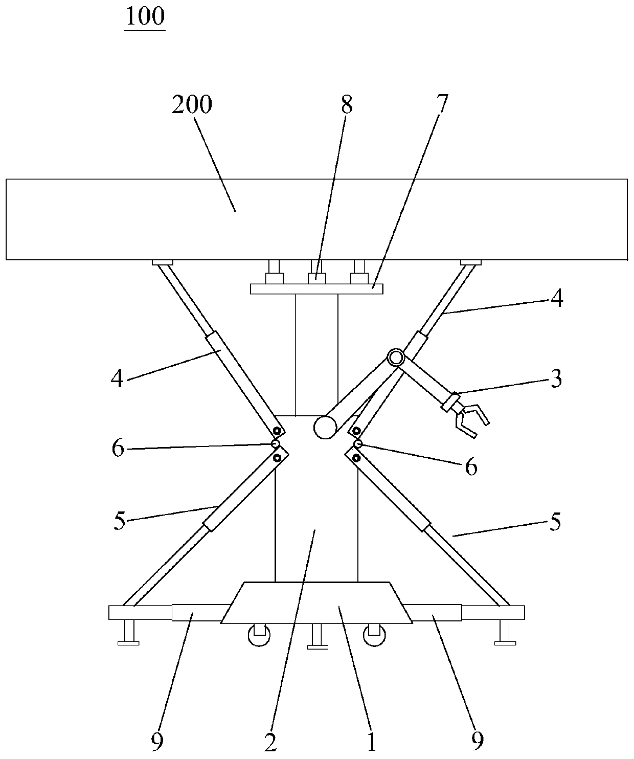
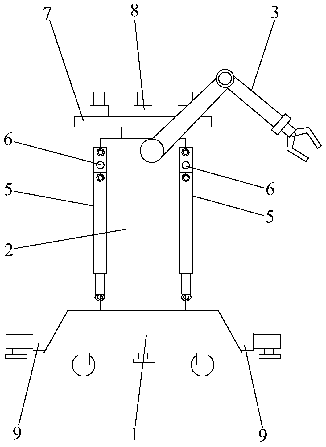
[0020] Such as figure 1 and figure 2 As shown, the building support robot 100 of the present invention includes a walking device 1, a lifting device 2, a grabbing device 3, a leveling device 4, a first supporting device 5 and a control system (not shown); the lifting device 2 is set On the walking device 1 and the output end of the lifting device 2 can be stretched out to support the building; the lifting device 2 is an oil cylinder. The grabbing device 3 is arranged on the walking device 1, and is used to install the construction mold 200 on the output end of the lifting device 2; the grabbing device 3 of the present invention is arranged on the cylinder body of the lifting device 2 Above, the grabbing device 3 is a manipulator. The levelin...


PUM


Abstract

The invention discloses a building supporting robot. The robot comprises a traveling device, a lifting device, a grabbing device, leveling devices and a control system, wherein the lifting device is arranged on the traveling device, the output end of the lifting device can stretch out to support a building, the grabbing device is arranged on the traveling device and used for installing a buildingmold at the output end of the lifting device, the leveling devices are arranged on at least one side of the lifting device, the output ends of the leveling devices can stretch out to support and adjust the two ends of the building mold, and the control system controls the actions of the traveling device, the lifting device, the grabbing device and the leveling devices. The building supporting robot can automatically travel and support a floor slab mold or a beam mold of a building, automatic construction is achieved, and the building construction efficiency is effectively improved.

Description

technical field [0001] The invention relates to a construction robot, in particular to a construction support robot. Background technique [0002] In traditional building construction, the assembled formwork is generally erected manually first, and then support rods are set under the formwork to support the formwork, and then the steel bars are manually bound into steel cages and steel plate mesh panels on site, and then the steel cages and steel bars are manually assembled. The stencil is put into the mold cavity, and the concrete material is poured. After the pouring concrete material is set, the support rods under the formwork are removed, and finally the formwork is removed. Therefore, in the traditional construction method, a large number of workers are required to erect formwork and support rods, which takes a long time to erect, has high labor intensity and low production efficiency. Contents of the invention [0003] The object of the present invention is to prov...

Claims


Application Information

Patent Timeline
IPC IPC(8): E04G25/00E04G25/04E04G25/06B25J9/16B25J11/00
CPCB25J9/1602B25J9/1679B25J11/00E04G25/00E04G25/04E04G25/06E04G2025/003
Inventor 不公告发明人
Owner 正如(广东)机器人科技有限公司
Why Eureka
Try Eureka