control valve group

A control valve and control port technology, applied in servo motor components, mechanical equipment, fluid pressure actuating devices, etc., can solve problems such as complex structure of hydraulic logic modules, and achieve the effect of solving complex structure, enhancing usability and simple structure

Active Publication Date: 2022-05-20
BEIJING LINKFORTUNE
View PDF6 Cites 0 Cited by
  • Summary
  • Abstract
  • Description
  • Claims
  • Application Information

AI Technical Summary

Problems solved by technology

[0005] The main purpose of the present invention is to provide a control valve group to solve the problem that the structure of the hydraulic logic module in the prior art is relatively complicated

Method used


Image

  • control valve group
  • control valve group
  • control valve group

Examples


Embodiment Construction

[0026] It should be noted that, in the case of no conflict, the embodiments in the present application and the features in the embodiments can be combined with each other. The present invention will be described in detail below with reference to the accompanying drawings and examples.

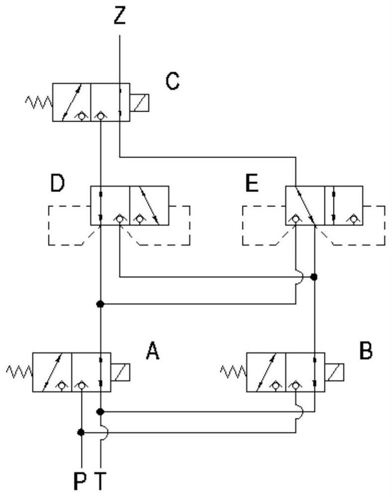
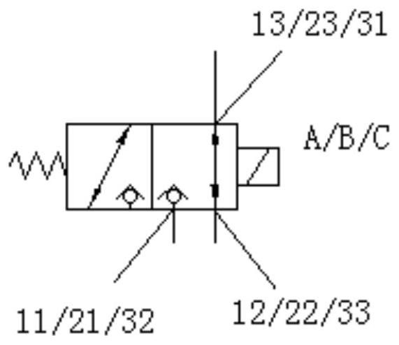
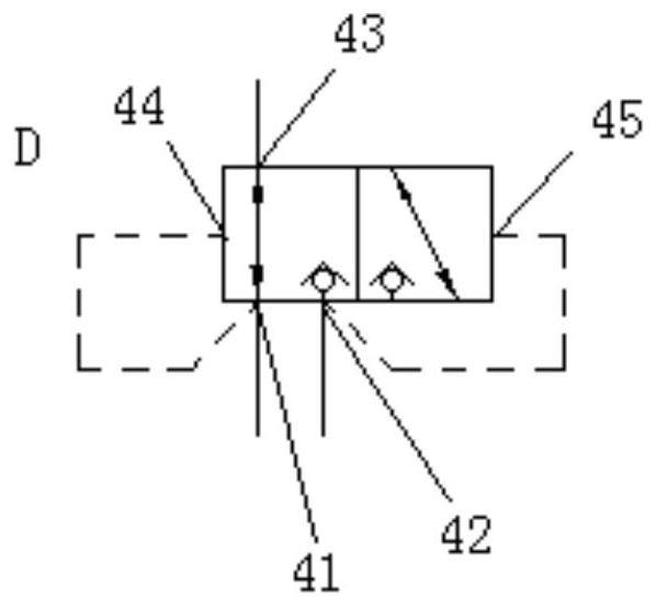
[0027] The invention provides a hydraulic control valve group, such as Figure 1 to Figure 6 As shown, the hydraulic control valve group includes: a first solenoid valve A, the first solenoid valve A has a first inlet port 11 for communicating with the pressure flow channel P and a first outlet port for communicating with the return channel T The flow port 12; the second solenoid valve B, the second solenoid valve B has a second inlet port 21 for communicating with the pressure flow channel P and a second outlet port 22 for communicating with the return channel T; the third Solenoid valve C, the third solenoid valve C has a control output port 31 for communicating with the output oil circuit Z...


PUM


Abstract

The present invention provides a control valve group, comprising: a first electromagnetic valve, the first electromagnetic valve has a first inlet for communicating with a pressure flow path and a first outlet for communicating with a return flow path; The second solenoid valve, the second solenoid valve has a second inlet port for communicating with the pressure flow path and a second outlet port for communicating with the return flow path; the third solenoid valve, the third solenoid valve has a second outlet port for communicating with the return flow path; The control output port communicated with the output oil circuit; the valve body assembly, the third solenoid valve is selectively communicated with the first solenoid valve and the second solenoid valve through the valve body assembly; wherein, when the first solenoid valve, the second solenoid valve and the When at least two solenoid valves in the third solenoid valve are in the energized state, the control output port communicates with the pressure flow path; In the power state, the control output port is connected with the return flow path.

Description

technical field [0001] The invention relates to the field of hydraulic control, in particular to a control valve group. Background technique [0002] In electro-hydraulic actuators, double solenoid valves are often used to construct "choose one from two" or "choose two from two" voting logic modules. In practical applications, the "choose one of two" voting focuses on the realization of safety, but the usability is slightly insufficient, and it is prone to misoperation; lead to the failure of the overall safety function. [0003] In the prior art, most of the components used to realize the voting of "choose one from two", "choose two from two" and "choose two from three" are relatively complicated components, and the manufacturing process is relatively complicated. Alternatively, in the prior art, a solenoid valve is used as the pilot to control multiple hydraulic control valves. This solution uses more components, and the hydraulic control valves generally have a slide va...

Claims


Application Information

Patent Timeline
Patent Type & Authority Patents(China)
IPC IPC(8): F15B13/02
CPCF15B13/02F15B2013/002
Inventor 陈岩钱伟
Owner BEIJING LINKFORTUNE
Why Eureka
Try Eureka