Combustor and fuel gas stove containing same

A burner and gas technology, applied in the direction of burner, gas fuel burner, combustion method, etc., can solve the problems that affect the normal use of gas stoves and cumbersome procedures

Active Publication Date: 2020-08-18
NINGBO FOTILE KITCHEN WARE CO LTD
View PDF3 Cites 0 Cited by
  • Summary
  • Abstract
  • Description
  • Claims
  • Application Information

AI Technical Summary

Problems solved by technology

[0003] The technical problem to be solved by the present invention is to provide a burner and a gas cooker containing it in order to overcome the cumbersome process of cleaning the flame hole of the gas cooker in the prior art and affect the normal use of the gas cooker

Method used


Image

  • Combustor and fuel gas stove containing same
  • Combustor and fuel gas stove containing same
  • Combustor and fuel gas stove containing same

Examples


Embodiment 1

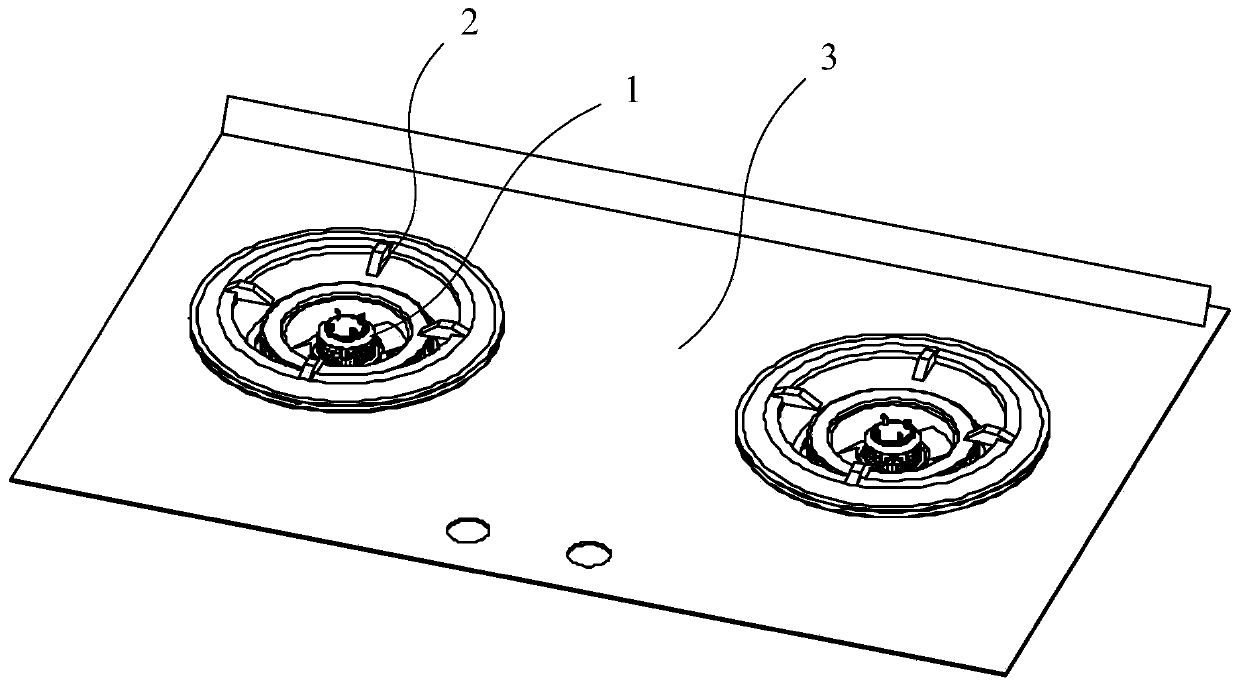
[0075] like figure 1 As shown, the present invention provides a gas cooker 10 , which includes a burner 1 , a pot support 2 and a cooker panel 3 . Wherein, both the burner 1 and the pot support 2 are arranged on the cooker panel 3 . The pot is placed on the pot support 2 and heated through the fire hole on the burner 1 .

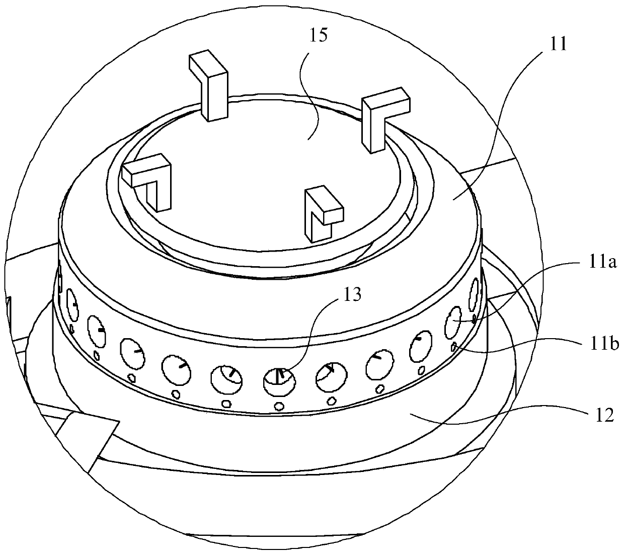
[0076] The burner 1 includes a fire cover 11 and a base 12. The fire cover 11 and the base 12 are combined up and down to form a gas chamber 1a inside. In this embodiment, the fire holes are all arranged on the fire cover 11, specifically including The main fire hole 11a and the flame-stabilizing hole 11b, the gas chamber 1a is connected to the main fire hole 11a and the flame-stabilizing hole 11b provided on the surface of the fire cover 11, so as to realize the purpose of heating the pot by supplying gas to these fire holes.

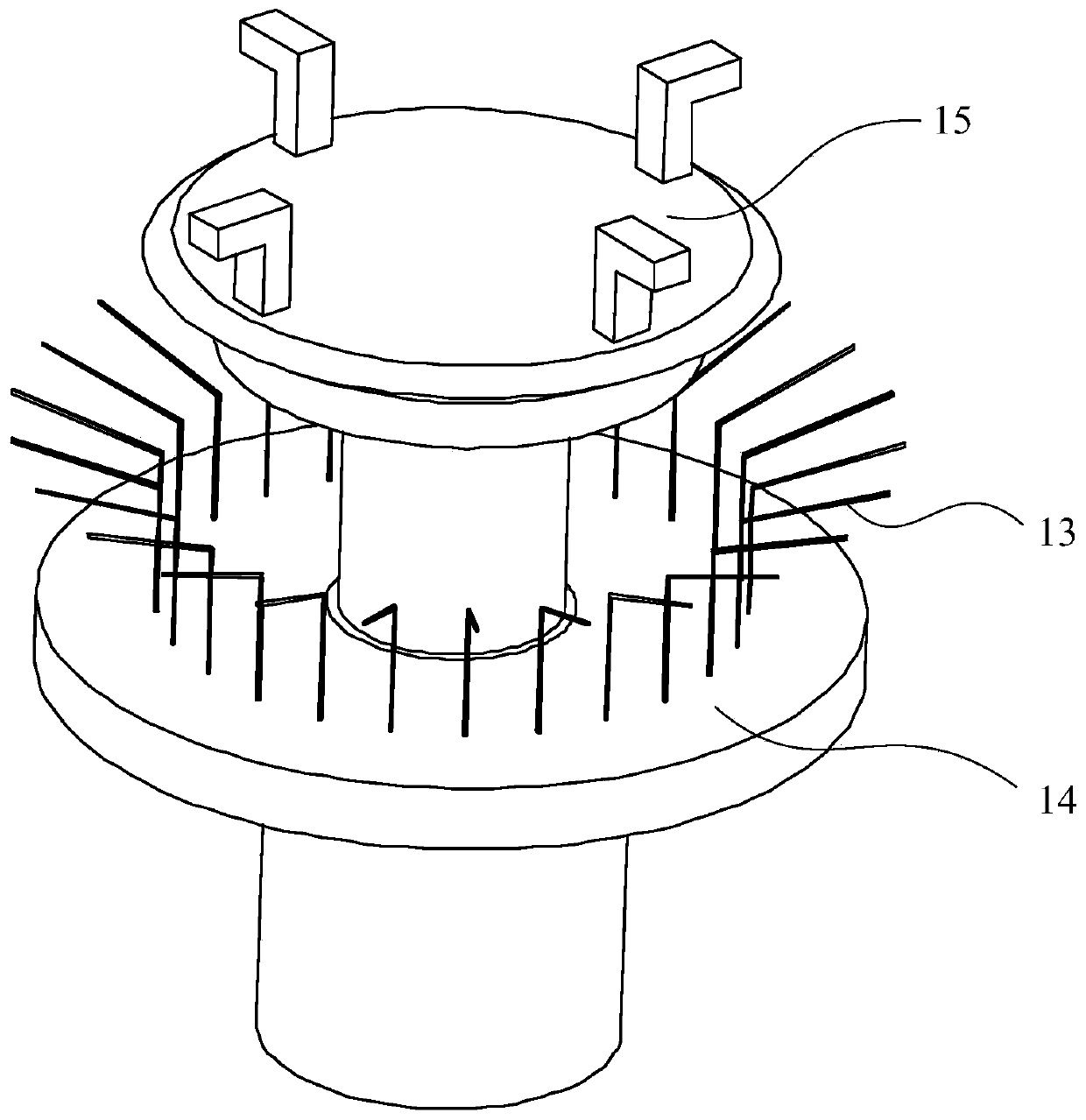
[0077] like figure 2 and image 3 As shown, the burner 1 also includes a cleaning part 13, a driving part 14 and a control par...

Embodiment 2

[0088] This embodiment also provides a gas cooker 10, the structure of the burner 1 is substantially the same as that of the burner 1 provided in Embodiment 1, the difference is that in this embodiment, as Figure 5 As shown, the main fire hole 11a and the flame-stabilizing hole 11b on the fire cover 11 are in a layout adjacent to each other, and two fire holes communicating with each other are provided between the fire hole channels of the main fire hole 11a and the flame-stabilizing hole 11b. Clean channel 11c.

[0089] At the same time, the cleaning part 13 is a rod-shaped structure narrower than the width of the cleaning passage 11c. When the cleaning part 13 moves relatively, the cleaning part 13 can move from the main fire hole 11a to the flame stabilization hole 11b through the cleaning passage 11c, so that the cleaning The part 13 can clean a plurality of fire holes.

[0090] Among them, such as Figure 5 As shown, the channel width D of the cleaning channel 11c is m...

Embodiment 3

[0093] This embodiment also provides a gas cooker 10, the structure of the burner 1 is substantially the same as that of the burner 1 provided in Embodiment 1, the difference is that in this embodiment, the cleaning part 13 is arranged on the outer ring of the burner 1 part of the fire hole, and the control part 15 is arranged on the upper surface of the pot support 2 . like Image 6 As shown, the main fire hole 11a on the outer ring is a groove-shaped fire hole 11d surrounding the entire outer ring fire cover 11, and the inner ring fire hole 5 of the gas cooker 10 transmits the flame to the groove-shaped fire hole through the fire transmission structure 4 11d, causing the outer ring part to be ignited.

[0094] like Figure 6-Figure 8 As shown, in this embodiment, the cleaning part 13 is an annular structure arranged in the slot-shaped fire hole 11 d, and the control part 15 arranged on the pot support 2 is connected to the cleaning part 13 through the driving part 14 . li...


PUM


Abstract

The invention discloses a combustor and a fuel gas stove containing the same. The combustor is provided with a fire hole and comprises a cleaning part and a driving part, wherein the cleaning part isarranged in the fire hole; the driving part is connected to the cleaning part and can drive the cleaning part to move relative to the fire hole; the cleaning part is arranged in the combustor, and thedriving part drives the cleaning part to move relative to the fire hole in the fire hole, so that cleaning of the fire hole is realized through the cleaning part; and besides, the cleaning part is hidden in the combustor, so that daily use of users is not affected. The cleaning mechanism is driven to move relative to the fire hole by operating a linking mechanism, so that cleaning of the inner part of the fire hole is realized; besides, the cleaning mechanism and the linking mechanism are integrated in the combustor, so that a user can conveniently clean the fire hole in time; problem of firehole blocking is effectively solved; and using experience of the users can be improved.

Description

technical field [0001] The invention relates to a burner and a gas cooker containing the burner. Background technique [0002] In the prior art, the fire hole of the gas cooker is easily blocked due to the inflow of overflow liquid or the accumulation of dirt, which affects the normal operation of the burner. Cleaning in the fire hole is very cumbersome and will affect the normal use of the gas cooker, resulting in a poor user experience. Contents of the invention [0003] The technical problem to be solved by the present invention is to provide a burner and a gas cooker including the burner to overcome the cumbersome process of cleaning the flame hole of the gas cooker in the prior art and affect the normal use of the gas cooker. [0004] The present invention solves the above technical problems through the following technical solutions: [0005] A burner having a fire hole, the burner comprising: [0006] a cleaning part, the cleaning part is arranged in the fire hole...

Claims


Application Information

Patent Timeline
Patent Type & Authority Applications(China)
IPC IPC(8): F23D14/46F23D14/58F24C3/08F24C3/12B08B1/00B08B13/00
CPCB08B1/001B08B13/00F23D14/46F23D14/58F24C3/085F24C3/126F23D2900/31018
Inventor 苏慧玲郑军妹俞瑜严力峰
Owner NINGBO FOTILE KITCHEN WARE CO LTD
Why Eureka
Try Eureka